


Parallel Circuits Explained: Voltage, Current, and Resistance Principles
In this article we unpack the three foundational rules that govern parallel electrical circuits: voltage equality, current addition, and resistance reduction. These concepts are critical for anyone designing or troubleshooting DC circuits.
- Voltage: Every component in a parallel network experiences the same potential difference.
- Current: The source delivers a total current that equals the algebraic sum of all branch currents.
- Resistance: The effective resistance of a parallel network is always lower than the smallest individual resistor.
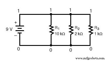
Below we illustrate each rule with a concrete example—a simple three‑resistor parallel circuit powered by a 9‑V battery.
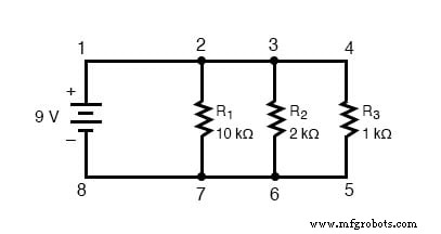
Rule 1: Voltage Equality in Parallel Circuits
Because the two nodes that define a parallel arrangement are electrically common, the voltage measured between them is identical across all branches. In the diagram above, the voltage across R1, R2, and R3 is 9 V—the same as the battery voltage.
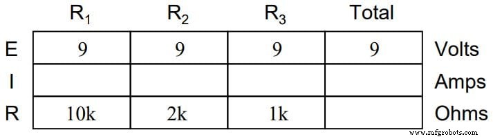
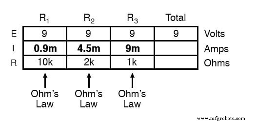
We can summarize the starting values in the following table (illustrated in the accompanying image):
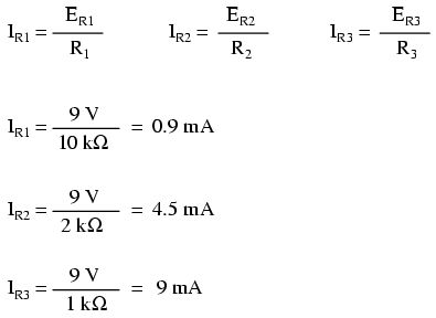
Rule 2: Current Addition in Parallel Circuits
Each branch draws a current that can be calculated with Ohm’s Law, I = V/R, using the shared 9 V. The individual currents are:
Because the current entering the positive terminal splits among the branches, the total current supplied by the battery is the sum of the branch currents:
In the example, the total current is 0.9 mA + 4.5 mA + 9 mA = 14.4 mA.
Calculating Total Resistance
Applying Ohm’s Law to the entire network gives the effective resistance:
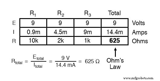
Note that the combined resistance (625 Ω) is lower than any single resistor—an expected result for parallel connections.
Mathematical Relationship for Parallel Resistance
The general formula is:
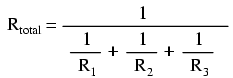
Adding more resistors simply extends the series of reciprocal terms on the right‑hand side.
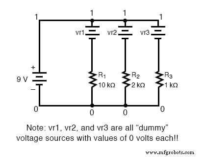
Simulating Parallel Circuits with SPICE
To validate calculations, we can model the circuit in SPICE. Because SPICE requires common node numbers, we re‑label the two shared nodes as 0 and 1:
Branch currents are measured through zero‑voltage sources inserted in series with each resistor:
The resulting netlist is shown below:
Parallel circuit
 v1 1 0
 r1 2 0 10k
 r2 3 0 2k
 r3 4 0 1k
 vr1 1 2 dc 0
 vr2 1 3 dc 0
 vr3 1 4 dc 0
 .dc v1 9 9 1
 .print dc v(2,0) v(3,0) v(4,0)
 .print dc i(vr1) i(vr2) i(vr3)
 .end
Running the simulation yields:
| Component | Voltage (V) |
|---|---|
| v1 (Battery) | 9.000E+00 |
| R1 | 9.000E+00 |
| R2 | 9.000E+00 |
| R3 | 9.000E+00 |
and current values:
| Component | Current (A) |
|---|---|
| v1 (Battery) | 9.000E+00 |
| IR1 | 9.000E-04 |
| IR2 | 4.500E-03 |
| IR3 | 9.000E-03 |
These results match the hand calculations, confirming the theory.
Key Takeaways
- All branches share the same voltage.
- Effective resistance decreases as more branches are added.
- Branch currents sum to the total source current.
Understanding these rules allows you to predict the behavior of any parallel network accurately.
Further Resources
- Parallel DC Circuits Practice Worksheet (with answers)
- Algebraic Equation Manipulation for Electric Circuits Worksheet
Industrial Technology
- Parallel Circuit Fundamentals: Voltage, Resistance, and Current Rules
- Understanding Simple Series Circuits: Key Principles and Practical Examples
- Building Resistor Circuits: From Alligator Clips to PCBs
- Voltage Divider Circuits: Mastering Series Resistor Analysis & Potentiometers
- Comprehensive Guide to Analyzing Series‑Parallel Resistor Networks
- Fundamentals of AC Circuit Calculations: From Resistance to Kirchhoff’s Laws
- Analyzing Parallel Resistor–Inductor AC Circuits: A Practical Guide
- Parallel Resistor–Capacitor AC Circuits: Analysis, Impedance, and Ohm’s Law
- Analyzing a Parallel R‑L‑C Circuit: Impedance, Current, and SPICE Simulation
- Parallel Tank Circuit Resonance: Theory, Calculations, and SPICE Verification