


Analyzing a Parallel R‑L‑C Circuit: Impedance, Current, and SPICE Simulation
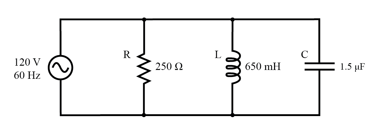
We can rearrange the same resistor, inductor, and capacitor from a series circuit into a parallel arrangement, yielding the following example.
Impedance in Parallel Components
Connecting the components in parallel does not alter their individual impedances. With the same supply frequency, the inductive and capacitive reactances remain unchanged.
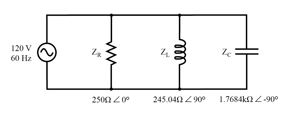
Expressing each element as an impedance (Z) allows us to build an analysis table and apply the rules of parallel circuits, analogous to the series case.
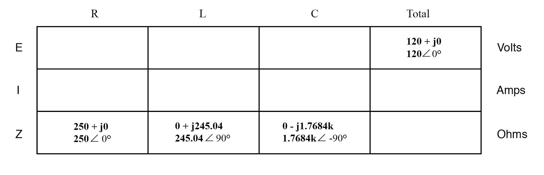
Because voltage is shared equally across all branches, we assign the total supply voltage to every column in the table.
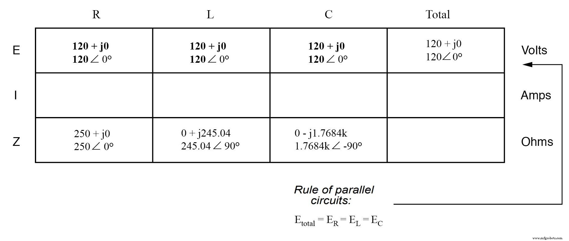
Applying Ohm’s law (I = E / Z) vertically yields the current through each branch.
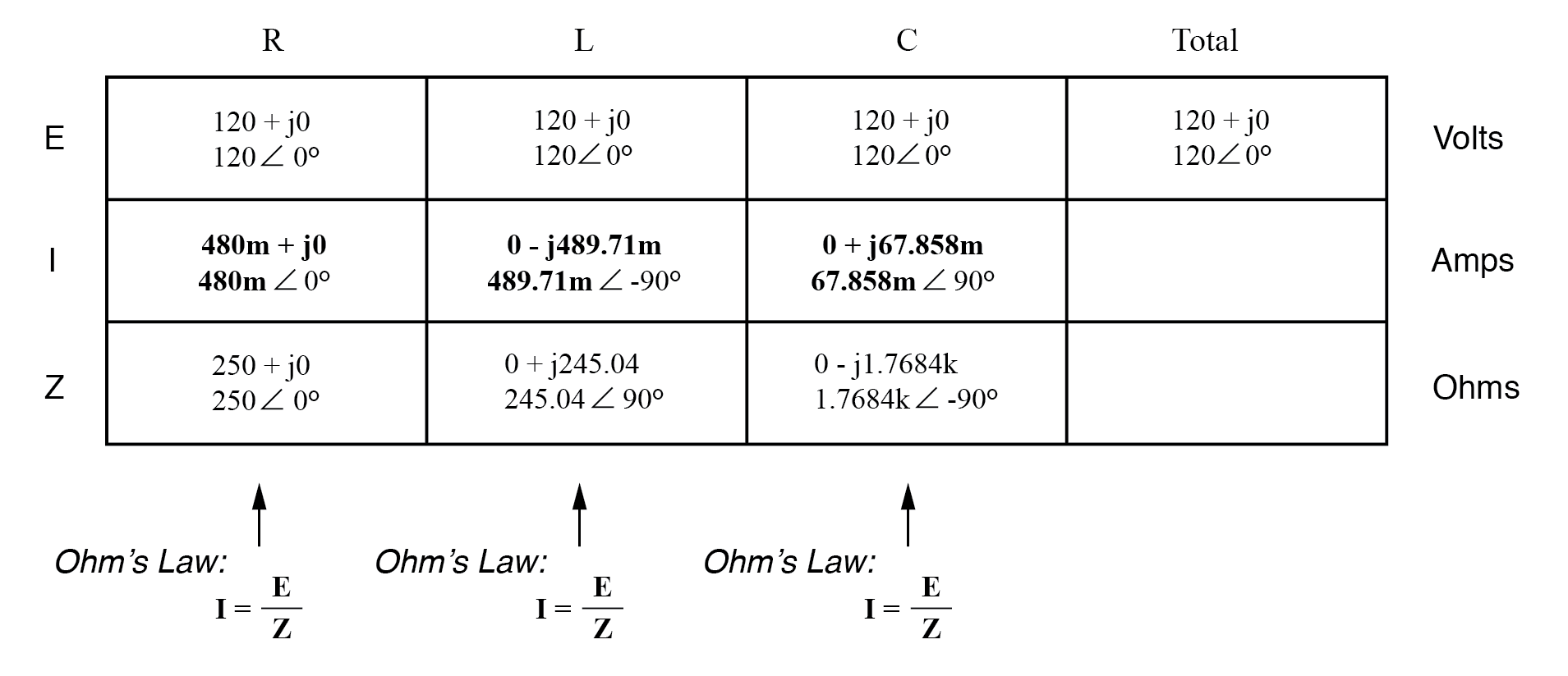
Calculating Total Current and Total Impedance
There are two effective strategies for determining the total current and overall impedance:
- Compute the equivalent parallel impedance using the formula
ZTotal = 1/(1/ZR + 1/ZL + 1/ZC), then find the total current withI = E / ZTotal. - Sum the individual branch currents to obtain the total current (the total current in a parallel circuit is the algebraic sum of all branch currents). Use Ohm’s law to derive the total impedance from the total voltage and total current:
Z = E / I.
While the first method requires handling complex reciprocals, the second method is often more straightforward, especially when working by hand.
Let’s validate the analysis with a SPICE simulation.
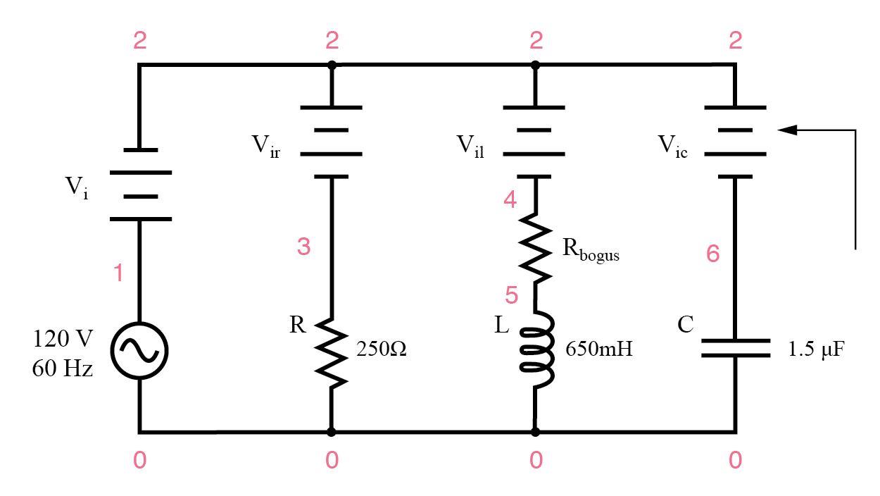
Below is the SPICE netlist for the circuit. Dummy voltage sources set to 0 V serve as measurement points for branch currents.
ac r-l-c circuit
v1 1 0 ac 120 sin

vi 1 2 ac 0
vir 2 3 ac 0
vil 2 4 ac 0
rbogus 4 5 1e-12
vic 2 6 ac 0
r1 3 0 250
l1 5 0 650m
c1 6 0 1.5u
.ac lin 1 60 60
.print ac i(vi) i(vir) i(vil) i(vic)

.print ac ip(vi) ip(vir) ip(vil) ip(vic)
.end
Sample output at 60 Hz:
freq          i(vi)       i(vir)      i(vil)      i(vic)
6.000E+01     6.390E-01   4.800E-01   4.897E-01   6.786E-02

freq          ip(vi)      ip(vir)     ip(vil)     ip(vic)
6.000E+01    -4.131E+01   0.000E+00  -9.000E+01   9.000E+01
Both calculation methods yield the same total current and impedance when performed correctly. For further practice, try the Series-Parallel Combination AC Circuits Worksheet.
RELATED WORKSHEET:
- Series-Parallel Combination AC Circuits Worksheet
Industrial Technology
- Parallel Circuit Fundamentals: Voltage, Resistance, and Current Rules
- Series and Parallel Component Calculations – Resistances, Inductances, Capacitances
- Understanding Series and Parallel Circuits: How They Work and Why They Matter
- Parallel Circuits Explained: Voltage, Current, and Resistance Principles
- Current Divider Circuits: Theory, Formula, and Practical Applications
- Understanding Series and Parallel Capacitors: How Capacitance Adds or Diminishes
- Series vs. Parallel Inductors: How Inductance Adds or Diminishes
- Analyzing Series-Parallel RC and RL Circuits with Complex Impedance
- Choosing the Right Battery Connection: Series, Parallel, and Series‑Parallel Configurations
- Integrating Total Productive Maintenance with Industrial IoT for Optimal Manufacturing Efficiency