


Understanding Series and Parallel Circuits: How They Work and Why They Matter
While a single battery and load resistor is easy to analyze, real-world electronics almost always involve multiple components. Understanding how these components are connected—either in series or in parallel—is essential for designing, troubleshooting, and optimizing circuits.
Series and Parallel Connections
When more than two components are involved, they can be arranged in one of two fundamental topologies: series or parallel. Each arrangement imparts distinct electrical characteristics that affect voltage distribution, current flow, and overall resistance.
Series Configuration
In a series circuit, components are linked end‑to‑end, creating a single, uninterrupted path for current. For example, three resistors (R1, R2, R3) connected in series form a chain from one battery terminal to the other.
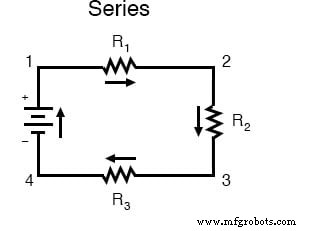
The subscript labels on each resistor are identifiers only; they do not denote the resistor’s value. Because there is one continuous path, the same current flows through every component, and the total resistance is the sum of the individual resistances.
Parallel Configuration
In contrast, a parallel circuit offers multiple independent paths for current. Three resistors can be arranged so that each provides a distinct branch between the same two voltage points.
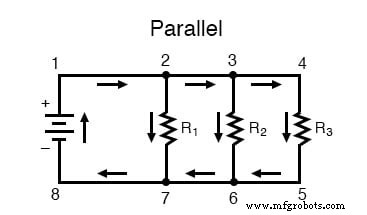
Each branch—such as the path through R1, the path through R2, and the path through R3—shares the same voltage across its ends. The total resistance is less than the smallest individual resistor, calculated using the reciprocal formula.
Series‑Parallel Hybrid Circuits
Real-world designs often combine series and parallel elements. A classic example has two loops: one that traverses R1 and a second that passes through R1, R2, and R3 together.
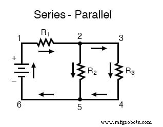
Here, R2 and R3 form a parallel pair, while R1 sits in series with their combined resistance. Analyzing such circuits requires breaking them into manageable series and parallel sections.
Key Concepts Recap
Series Connection
Components are connected end‑to‑end, yielding a single current path and cumulative resistance.
Parallel Connection
Components share the same two nodes, creating multiple paths. Each branch sees the full supply voltage, and the overall resistance decreases.
- Series: one continuous current path.
- Parallel: multiple paths, shared voltage, reduced total resistance.
- Branch: a single path in a parallel circuit, typically defined by one load component.
For hands‑on practice, download the Series‑Parallel DC Circuits Worksheet to reinforce these concepts.
Industrial Technology
- Understanding Electric Circuits: Continuous Charge Flow and the Impact of Breaks
- Understanding Simple Series Circuits: Key Principles and Practical Examples
- Understanding Series-Parallel Circuits: How They Work & Why They Matter
- Comprehensive Guide to Analyzing Series‑Parallel Resistor Networks
- Understanding Series and Parallel Capacitors: How Capacitance Adds or Diminishes
- Series vs. Parallel Inductors: How Inductance Adds or Diminishes
- Series RC Circuit Analysis: Impedance, Phase Relationships, and SPICE Validation
- Parallel Resistor–Capacitor AC Circuits: Analysis, Impedance, and Ohm’s Law
- Mastering Series RLC Circuit Analysis: From Impedance to KVL
- Inside the Manufacturing of Electronic Circuits