


Comprehensive Guide to Analyzing Series‑Parallel Resistor Networks
Step‑by‑Step Method for Analyzing Series‑Parallel Resistor Circuits
Master the art of finding every voltage drop, current, and power dissipation in a mixed series‑parallel network. The process follows a logical, repeatable strategy that mirrors textbook methods and real‑world practice.
- Step 1: Identify all resistor groups that are strictly in series or strictly in parallel.
- Step 2: Replace each identified group with a single equivalent resistor and redraw the circuit. Update your working table to include a new column for each equivalent value.
- Step 3: Repeat steps 1–2 until the entire network collapses into one equivalent resistor.
- Step 4: Compute the total current with Ohm’s law:
I = E / R, whereEis the source voltage andRis the final equivalent resistance. - Step 5: Work backwards through the reduction sequence, inserting the known total voltage and current at each stage.
- Step 6: Apply Ohm’s law (
V = I RorI = V / R) to determine missing voltages or currents in the simplified circuit. - Step 7: Continue the backward substitution until every element in the original circuit has a calculated voltage and current.
- Step 8: Calculate power for each resistor with
P = V IorP = I² R.
Illustrative Example
Visual learning often clarifies the reduction process. Refer to the diagrams below for a concrete example.
Calculating Parallel Equivalents
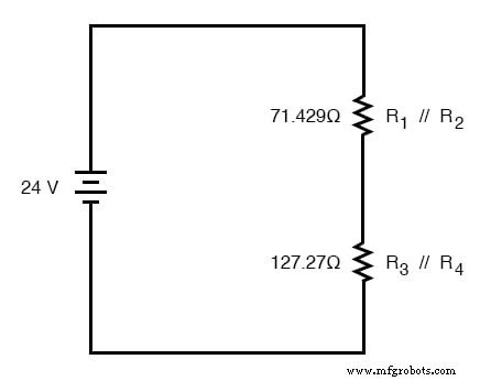
In the sample circuit, R1 and R2 are in parallel, as are R3 and R4. Convert each pair to a single resistor and redraw:
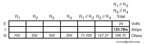
The parallel notation (//) indicates the use of the formula 1 / (1/R1 + 1/R2). The top equivalent is 71.429 Ω, while the bottom is 127.27 Ω.
Expand the working table to include these equivalents:
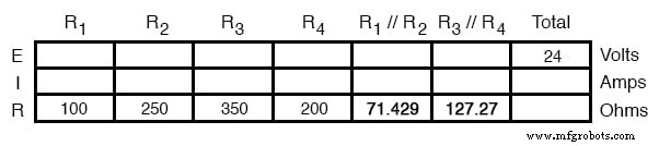
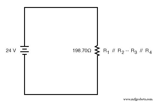
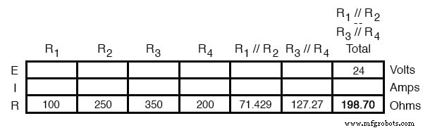
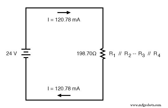
The network is now a simple series chain of two resistors. Adding them yields a total resistance of 198.70 Ω.
Redraw the circuit as a single resistor and record the value in the “Total” column of the table. The symbol “—” denotes series, while “//” denotes parallel.
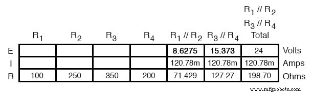
Determining Currents and Voltages
Compute the total current: I = 24 V / 198.70 Ω ≈ 0.1208 A (120.78 mA).
Mark this current in the equivalent circuit:
Reverse the reduction: in the stage where the two parallel groups are in series, the same current flows through each equivalent resistor. Copy the total current into the corresponding columns.
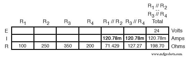
Apply Ohm’s law to find voltage drops across the two equivalent resistors:
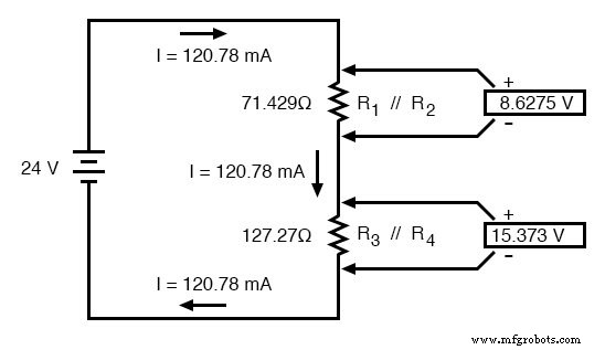
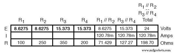
Since each pair is in parallel, the voltage across the pair equals the voltage across each individual resistor. Transfer these values back into the table for the original resistors.
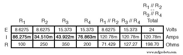
Finally, compute the current through each resistor using I = V / R:
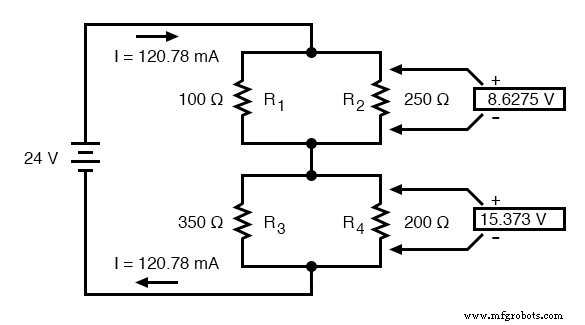
Annotating the Schematic
Insert the calculated voltages and currents directly into the schematic for a clear visual reference:
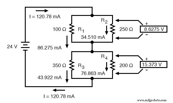
Verify consistency: the currents through R1 and R2 should sum to the total 120.78 mA, and likewise for R3 and R4.
Validating with SPICE Simulation
A SPICE model offers an independent check of the hand‑calculated values. The netlist below includes current‑sense voltage sources (zero volts) to capture each resistor’s current.
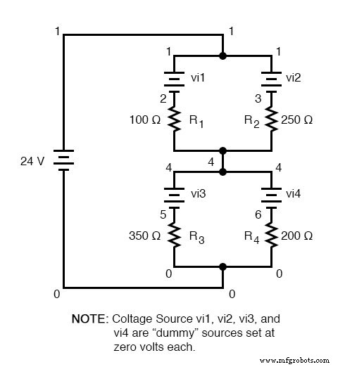
series-parallel circuit
 v1 1 0
 vi1 1 2 dc 0
 vi2 1 3 dc 0
 r1 2 4 100
 r2 3 4 250
 vi3 4 5 dc 0
 vi4 4 6 dc 0
 r3 5 0 350
 r4 6 0 200
 .dc v1 24 24 1
 .print dc v(2,4) v(3,4) v(5,0) v(6,0)
 .print dc i(vi1) i(vi2) i(vi3) i(vi4)
 .end
The SPICE output confirms the hand‑derived figures:
| v1 | v(2,4) | v(3,4) | v(5) | v(6) |
|---|---|---|---|---|
| 2.40E+01 | 8.63E+00 | 8.63E+00 | 1.54E+01 | 1.54E+01 |
| v1 | i(vi1) | i(vi2) | i(vi3) | i(vi4) |
|---|---|---|---|---|
| 2.40E+01 | 8.63E-02 | 3.54E-02 | 4.39E-02 | 7.69E-02 |
All values align perfectly with the analytical results.
Key Takeaways
- Reduce the network to a single equivalent resistor, noting each step.
- Calculate the total resistance and the resulting current.
- Work backwards, assigning voltages and currents at each stage.
- Confirm results with a SPICE simulation for added confidence.
Related Worksheets
- Algebraic Equation Manipulation for Electric Circuits Worksheet
- Series‑Parallel DC Circuits Worksheet
Industrial Technology
- Key Rules for Series Circuits: Current, Resistance, and Voltage
- Parallel Circuit Fundamentals: Voltage, Resistance, and Current Rules
- Understanding Series and Parallel Circuits: How They Work and Why They Matter
- Understanding Simple Series Circuits: Key Principles and Practical Examples
- Parallel Circuits Explained: Voltage, Current, and Resistance Principles
- Building Resistor Circuits: From Alligator Clips to PCBs
- Understanding Series-Parallel Circuits: How They Work & Why They Matter
- Building Series‑Parallel Resistor Circuits: From Breadboards to Terminal Strips
- Series RC Circuit Analysis: Impedance, Phase Relationships, and SPICE Validation
- Parallel Resistor–Capacitor AC Circuits: Analysis, Impedance, and Ohm’s Law