


Network Analysis Explained: Advanced Techniques for Complex Electrical Circuits
In electrical engineering, network analysis refers to the systematic application of mathematical principles to determine currents, voltages, and resistances in a circuit composed of interconnected components. While many simple circuits can be reduced using series‑parallel rules, real‑world designs often include multiple voltage sources or configurations that resist such simplification. This chapter outlines the foundational techniques used when conventional reduction fails.
Analyzing a Simple Circuit
We begin with a classic series‑parallel network to illustrate the basic approach.
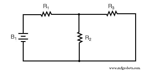
First, calculate the equivalent resistance of R2 and R3 in parallel, then add R1 in series. With the total resistance known, Ohm’s law (I = V/R) gives the overall current. That current is then distributed to compute voltage drops across each element—an elementary, step‑by‑step procedure.
When Series‑Parallel Reduction Fails
Two‑Battery Circuit
Introducing a second source dramatically changes the analysis:
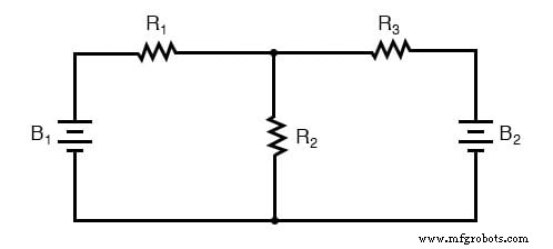
Here, R2 and R3 are no longer purely parallel because battery B2 branches through R3. In fact, no pair of resistors lies directly in series or parallel, eliminating the possibility of a simple reduction. The absence of a single “total” resistance means we cannot apply Ohm’s law directly to find a unique current.
Unbalanced Bridge Circuit
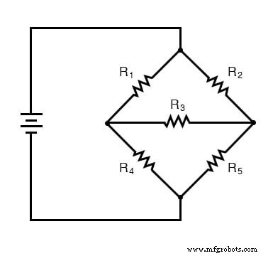
Consider a bridge network that is not balanced (R1/R4 ≠ R2/R5). In a balanced bridge, the middle resistor R3 carries no current and the network collapses into two parallel branches. With an imbalance, current flows through R3, so R1 is not in series with R4 and R2 is not in series with R5. Likewise, the pairs (R1,R2) and (R4,R5) are not parallel. Consequently, the network cannot be simplified by series/parallel rules, and multiple unknowns arise.
The core difficulty is that more than one variable—such as node voltages or branch currents—must be determined simultaneously. In contrast, a pure series/parallel circuit yields a single unknown (total current) once the overall resistance is known.
To handle these situations, engineers turn to the mathematical framework of simultaneous equations or systems of equations. By writing Kirchhoff’s voltage and current laws for each loop or node, we generate a set of equations equal in number to the unknowns. Solving this system yields all required currents and voltages. Modern scientific calculators or symbolic software can handle these calculations efficiently, making the process approachable.
In later sections we’ll introduce network theorems—thevenin, norton, superposition, and others—that often bypass the need for full systems of equations by reducing the network to simpler equivalent forms.
Key Takeaways
- Not all circuits are reducible via simple series/parallel rules; complex topologies introduce multiple unknowns.
- Simultaneous equations provide a systematic solution method for these networks.
Additional Resources
- DC Branch Current Analysis Worksheet
- Series‑Parallel DC Circuits Worksheet
Industrial Technology
- Component Failure Analysis: Troubleshooting Techniques for Series and Parallel Circuits
- Understanding Series-Parallel Circuits: How They Work & Why They Matter
- Understanding Measurement Statistical Analysis (MSA): Purpose, Tools, and Impact
- Understanding Cloud Networking: Key Concepts & Benefits
- Understanding Branch Circuits: Function, Types, and Importance
- Operation Analysis: Unlocking Business Efficiency & Reducing Waste
- Understanding Distribution Boards: Key Functions and Modern Features
- Understanding Reverse Voltage: Causes, Effects, and Safety Tips
- Understanding Feedback Circuits: How Signal Looping Enhances Electrical Stability
- How to Safely Recycle and Repurpose Old Circuit Boards