


Strain Gauges: Precision Measurement of Mechanical Stress
When a slender, conductive metal strip is stretched, it becomes thinner and longer, increasing its end‑to‑end electrical resistance. Conversely, compressing the strip (without buckling) widens and shortens it, reducing resistance. By keeping the deformation within the metal’s elastic limit, the strip’s resistance changes become a reliable indicator of applied mechanical force.
What Is a Strain Gauge?
A device that exploits this principle is called a strain gauge. Widely used in mechanical engineering R&D, strain gauges enable the quantification of stresses in everything from industrial machinery to aircraft components. Typical gauges are smaller than a postage stamp and resemble the figure below:
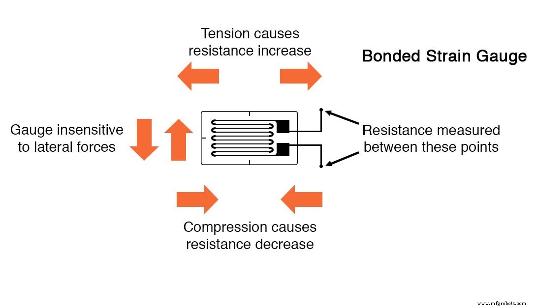
Strain gauge conductors are ultra‑thin: if fabricated as round wire, they measure roughly 1/1000 inch in diameter. Alternatively, a metallic film can be deposited onto a non‑conducting substrate—known as the carrier—to form a bonded gauge. Bonding a gauge to a test specimen (the structure under test) is a skilled procedure; accurate, stable strain readings depend on meticulous surface preparation, adhesive selection, and alignment.
Strain Gauge Resistance
Unstressed gauges typically exhibit resistances ranging from 30 Ω to 3 kΩ. Because the elastic limits of both the gauge and the specimen restrict the maximum allowable strain, the corresponding resistance change is often only a few tenths of a percent. Consequently, detecting such minute variations demands extremely precise instrumentation; otherwise, any excessive force would permanently deform the gauge or specimen, rendering the measurement invalid.
Bridge Measurement Circuit
To capture these subtle resistance changes, a Wheatstone‑type bridge circuit is employed. Unlike the classic bridge that seeks a null condition, a strain‑gauge bridge reports strain through the degree of imbalance, measured by a high‑resolution voltmeter positioned at the bridge’s center:
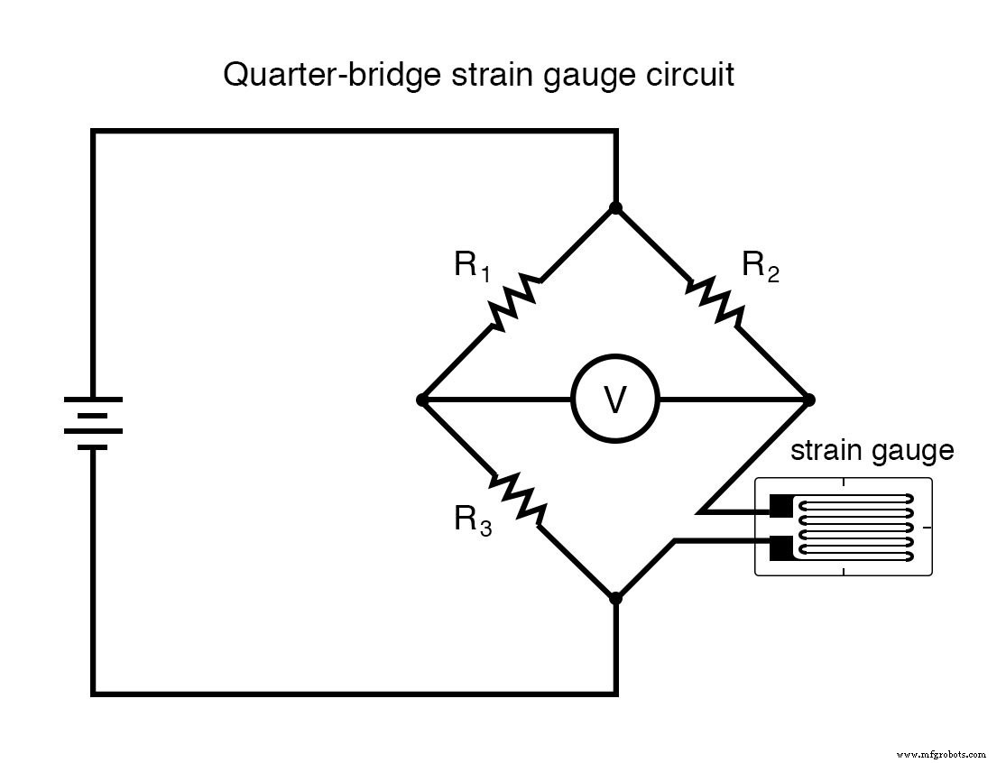
In a typical quarter‑bridge configuration, the rheostat arm (R2) is pre‑tuned to the gauge’s unstressed resistance, while the two ratio arms (R1 and R3) are matched. When the gauge experiences tension or compression, its resistance shifts, unbalancing the bridge and producing a measurable voltage.
Wire Resistances
Because the gauge and its leads can be separated by a significant distance, the series resistance of the wiring (Rwire1 and Rwire2) can introduce errors by contributing to the lower rheostat arm’s total resistance. This stray resistance can be misinterpreted as strain by the voltmeter.
While it is impossible to eliminate this effect entirely, it can be mitigated by adding a third lead that connects the voltmeter’s positive terminal directly to the gauge’s top node:
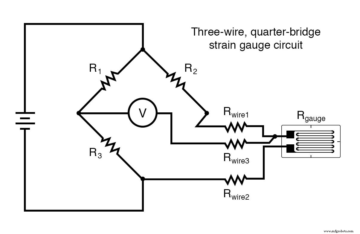
With the third lead carrying negligible current, its resistance does not affect the voltage division. This arrangement effectively bypasses the upper lead’s resistance, leaving only the lower lead’s series resistance to influence the measurement—halving the potential error relative to the two‑wire setup.
Temperature Compensation
All conductors exhibit some temperature‑dependent resistance change, which can mask true strain signals. A robust solution is to employ a dummy gauge in place of the rheostat arm (R2) so that both arms of the bridge change resistance proportionally with temperature. The circuit then becomes immune to temperature fluctuations because any common‑mode resistance change cancels out:
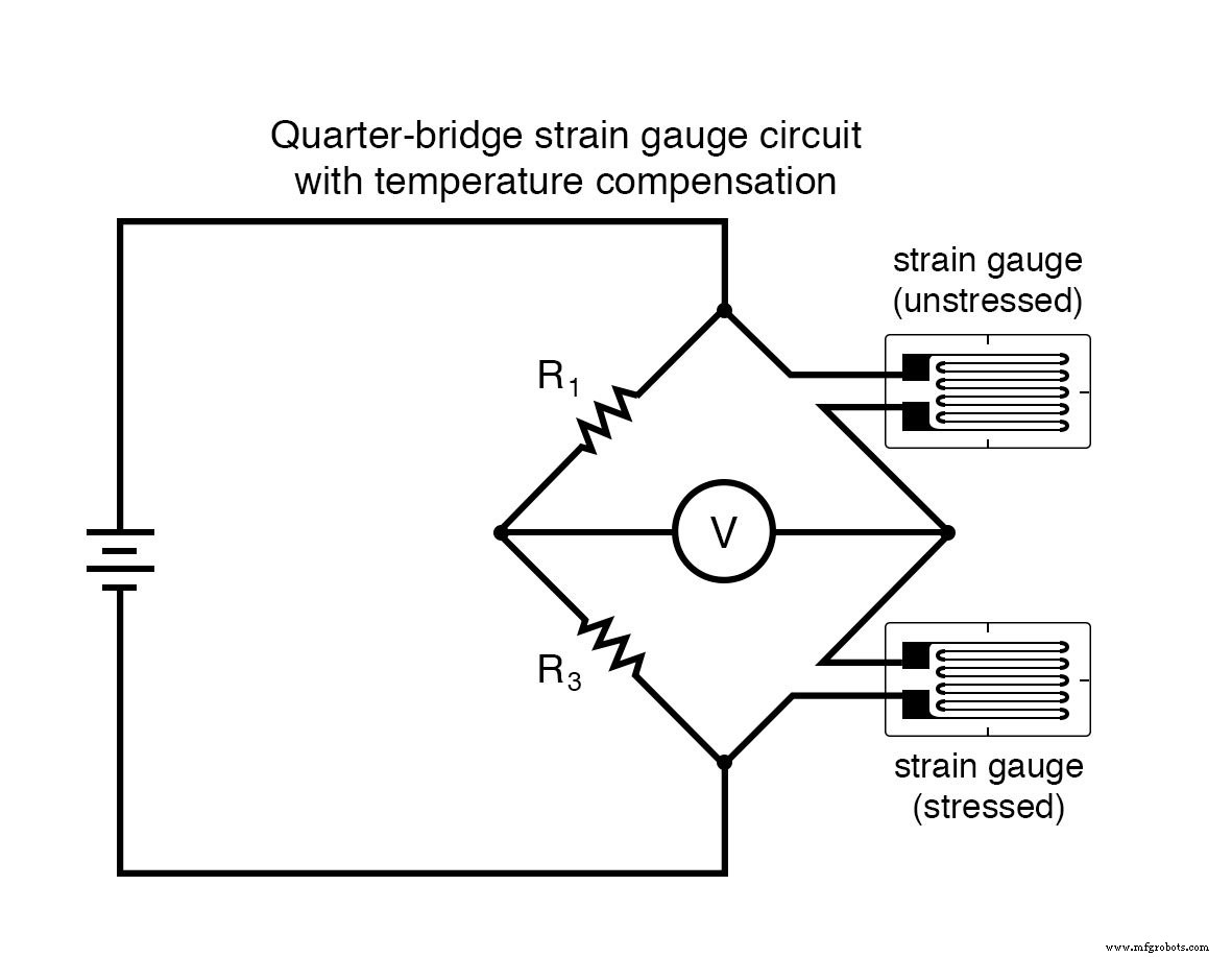
Here, R1 and R3 remain matched, and the two gauges are bonded to the same specimen. Only the gauge exposed to mechanical strain (the active gauge) varies in resistance with applied force; the dummy gauge stays fixed, ensuring that the bridge imbalance reflects strain alone.
Quarter‑Bridge and Half‑Bridge Configurations
Although only one gauge in the dummy‑gauge setup responds to strain, the configuration is still termed a quarter‑bridge. By positioning a second active gauge on the opposite side of the specimen—so that one gauge experiences compression while the other experiences tension—both gauges become strain‑sensitive. This half‑bridge arrangement doubles the sensitivity and further suppresses temperature effects, since both gauges still share identical temperature coefficients.
Typical bonding layouts for a half‑bridge are illustrated below:
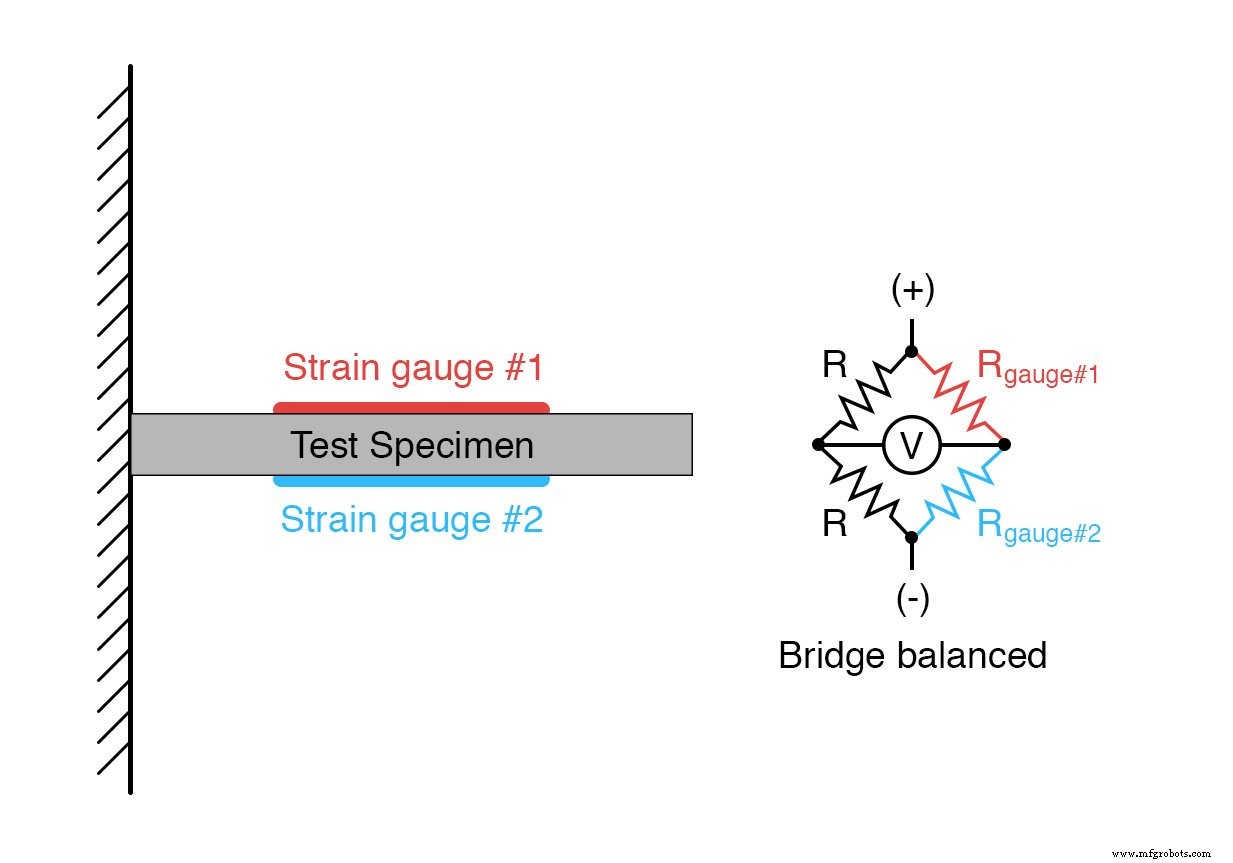
When a downward load is applied, gauge #1 elongates while gauge #2 compresses, generating a differential resistance that drives the bridge imbalance.
Full‑Bridge Circuits
When the specimen can accommodate complementary gauge pairs on all four arms, a full‑bridge is employed. This topology maximizes sensitivity and linearity because every arm actively tracks strain, ensuring that the output voltage is directly proportional to applied force:
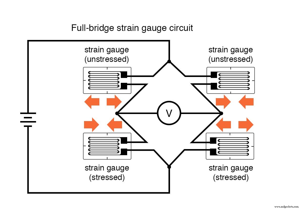
Full‑bridge circuits are preferred whenever feasible. They offer superior accuracy and a linear response compared to quarter‑ or half‑bridge arrangements, which provide only approximate proportionality unless the resistance change remains infinitesimal relative to the nominal gauge resistance.
Strain‑gauge systems are often sold as integrated load cells—sealed housings containing both the gauge elements and the bridge resistors, protected from environmental factors and ready for mechanical attachment to a structure.
Because strain‑gauge technology can become intricate, a dedicated treatise is beyond this article’s scope, but the principles outlined above form the foundation for reliable mechanical stress measurement.
Review
- A strain gauge is a thin metal strip that changes resistance under elastic deformation, enabling force measurement.
- Resistance changes are read with a bridge circuit, which provides high precision and temperature compensation.
Related Worksheets
- DC Bridge Circuits Worksheet
Industrial Technology
- Comprehensive Copper Wire Gauge Table – Sizes, Diameters, Areas & Weights
- Precision Pressure Gauges for Industrial & Safety Applications
- The Ultimate Sheet Metal Gauge Chart: Accurate Thickness Reference for Engineers and Fabricators
- Understanding Depth Gauges: Types, Uses, and Accurate Hole Depth Measurement
- What Is a Drill Gauge? A Professional Guide to Identifying Drill Bit Sizes
- Digital Height Gauges: Accurate Measurement & Quality Control Solutions
- How Pressure Gauges Work: Types, Functions, and Benefits
- Mastering Strain Gauges: How They Convert Mechanical Stress into Precise Electrical Signals
- The Pirani Gauge Explained: Working Principles, Applications, and Benefits
- Understanding Compressor Gauges: Key Insights for Reliable Operation