


pH Measurement: Fundamentals, Electrodes, and Best Practices
A critical parameter in many chemical processes—industrial, pharmaceutical, manufacturing, and food production—is the pH of a liquid solution. Accurate pH measurement ensures product quality, safety, and regulatory compliance.
The pH scale ranges from 0 for a strong acid to 14 for a strong caustic, with 7 representing neutral pure water. This logarithmic scale is illustrated in the figure below.
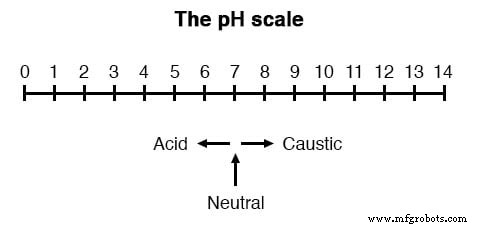
pH is defined as the negative base‑10 logarithm of the hydrogen‑ion activity (H⁺) in moles per liter:
- 10-12 mol L⁻¹ H⁺ → pH 12
- 10-3 mol L⁻¹ H⁺ → pH 3
Extremely acidic or alkaline solutions can have pH values below 0 or above 14, but these are highly concentrated and reactive.
pH Electrodes
While colorimetric methods (e.g., litmus paper) provide a qualitative indication, precise process control requires a potentiometric sensor. A pH electrode pair generates a voltage directly proportional to the solution’s pH:
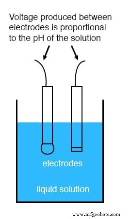
At neutral pH (7) the electrode pair exhibits 0 V. Acidic solutions produce a voltage of one polarity; alkaline solutions produce the opposite polarity. The slope is ideally 59.16 mV per pH unit at 25 °C.
Measurement Electrode
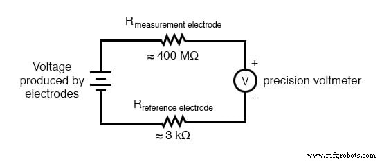
The measurement electrode is a glass membrane doped with lithium ions. This ion‑selective barrier allows H⁺ to migrate while blocking other ions, generating the pH‑dependent voltage across the glass thickness. Because glass is an excellent insulator, the electrode presents a resistance ranging from 10 MΩ to 900 MΩ.
Reference Electrode
The reference electrode contains a stable, neutral (pH ≈ 7) potassium chloride buffer and a porous junction that exchanges ions with the test solution. This design provides a low‑resistance (~kΩ) pathway, establishing a zero‑voltage reference point for the circuit. Using a simple metal wire would introduce a significant contact potential, corrupting the measurement.
Illustrations of the electrode construction:
Measurement electrode: 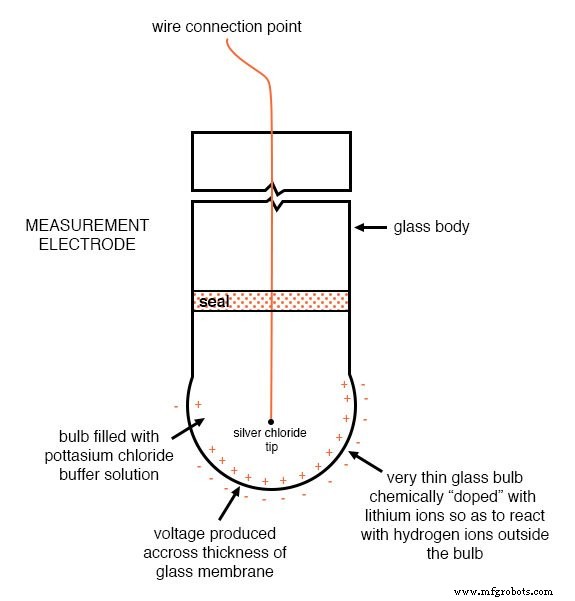
Reference electrode: 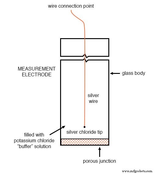
The high resistance of the glass electrode means that even a microampere of current can produce a sizable voltage drop, masking the true electrode voltage. Therefore, the measuring instrument must have an extremely high input impedance or use a null‑balance (potentiometric) configuration that draws no current.
Typical solutions:
- High‑impedance digital voltmeters (≥1012 Ω).
- Null‑balance potentiometers that adjust a reference voltage until the detector reads zero.
Wiring best practices mirror those of thermocouples: use clean, gold‑plated contacts and keep lead lengths short (≤10 ft) to minimize noise and potential drift.
Key considerations for reliable pH measurement:
- Electrode lifespan: Dependent on application severity; ranges from weeks to over a year.
- Measurement electrode failure: Indicated by a lack of voltage change (~59 mV/pH) or slow response to rapid pH shifts.
- Reference electrode drift: Causes offset errors; typically due to buffer depletion or junction blockage.
- Logarithmic scale impact: A 1‑unit change at high pH (e.g., 12→13) represents a different chemical change than at low pH (2→3). Control engineers must account for this nonlinearity.
- Hazardous conditions: High temperature, extreme pH, high ionic strength, abrasion, HF, and surface coatings can damage the glass membrane.
- Temperature compensation: Temperature affects both the electrode response and the solution’s true pH. Incorporate a temperature probe to correct the measured voltage.
Emerging technologies, such as field‑effect transistor (FET) sensors, promise to bypass the high‑resistance challenge by measuring ion‑permeable membrane potentials directly. Though still under development, FET‑based pH probes could offer improved speed and durability.
Quick Reference
- pH = –log₁₀[H⁺] (mol L⁻¹)
- Scale: 0 (strong acid) – 7 (neutral) – 14 (strong caustic)
- Measurement electrode: lithium‑doped glass, generates ~59 mV/pH
- Reference electrode: KCl buffer + porous junction, provides zero‑voltage reference
- Measurement requires a high‑impedance voltmeter or null‑balance setup
Industrial Technology
- Precision 4‑Wire Resistance Measurement: The Kelvin Method
- Differential Equations: Solving for Functions, Not Numbers
- Minterm vs Maxterm: A Comprehensive Guide to Karnaugh‑Map Simplification
- Optimizing Photodiode Measurement Circuits for Low‑Light Sensitivity
- Precision 4‑Wire Kelvin Resistance Measurement: Eliminating Wire‑Resistance Errors
- Magnetic Units of Measurement Explained: Fundamentals, SI, and Practical Equivalents
- Measuring Frequency and Phase in AC Power Systems
- Accurate Power Measurement in AC Circuits: From Electrodynamometers to Hall‑Effect Sensors
- Measuring Power Quality: Understanding Harmonics and Their Impact on AC Systems
- Industry 4.0 Insights: Q&A with Bosch.IO’s Verena Majuntke on IoT, Automation, and the Future Factory