


Precision 4‑Wire Kelvin Resistance Measurement: Eliminating Wire‑Resistance Errors
When measuring a component that lies far from an ohmmeter, the resistance of the connecting leads can dominate the reading. Because an ohmmeter registers the total loop resistance—including the subject’s resistance and the resistance of the long wires (Rwire + Rsubject)—the measured value often overstates the true resistance of the component. This becomes especially problematic for low‑resistance parts or when the leads extend over hundreds of feet.
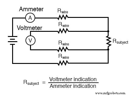
To isolate the subject resistance (Rsubject) from the wire resistance, a 4‑wire (Kelvin) technique uses separate current‑carrying and voltage‑sensing paths. By measuring the current through the component with an ammeter and the voltage drop across it with a voltmeter, Ohm’s law (R = V/I) can be applied without the wire resistance affecting the result.
In this arrangement the voltmeter is placed close to the ammeter, connected across the subject resistance via its own pair of wires. Because the voltmeter draws negligible current, the voltage dropped along these sensing wires is virtually zero, so the voltmeter reads almost the same value as if it were directly across the component.
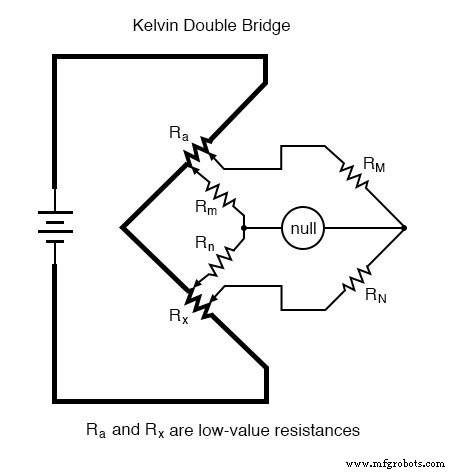
Below is a diagram illustrating the basic Kelvin configuration, where the current‑carrying conductors (bold) and the voltage‑sensing conductors (thin) are kept separate to avoid any voltage drop from the leads in the voltage measurement.
Kelvin Clips and 4‑Wire Connections
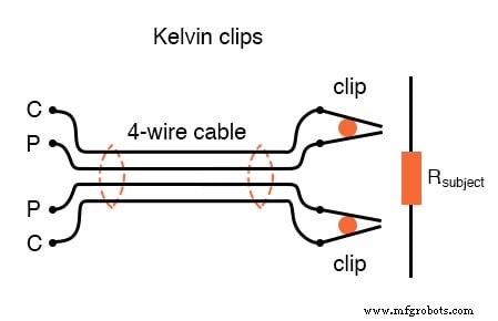
Specialized “Kelvin clips” provide insulated contact points for the current and voltage terminals. Unlike standard alligator clips, the two halves of a Kelvin clip’s jaw are isolated at the hinge and only meet at the tips. This ensures that the current flowing through the current terminals does not travel through the voltage terminals, eliminating unwanted voltage drops.
The same principle is applied in precision shunt resistors and standard resistors used in metrology. These devices feature four terminals: two large ones for current flow and two small ones for voltage sensing. This configuration guarantees that the voltmeter measures only the voltage across the resistor itself.
Standard Resistors in a 4‑Wire Setup
High‑accuracy standard resistors—often maintained in temperature‑controlled environments—also use 4‑wire connections. The diagram below shows a 1 Ω standard resistor immersed in an oil bath, with its two outer terminals for current and two inner terminals for voltage.
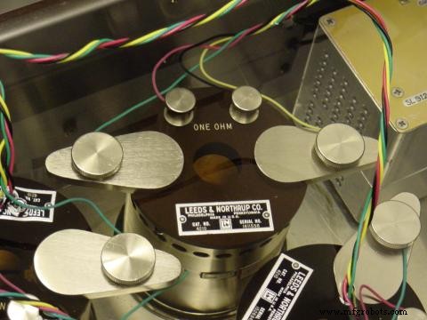
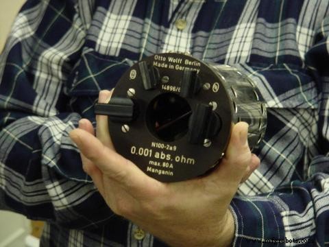
Historical 0.001 Ω standard resistors exhibit the same four‑terminal arrangement, demonstrating the long‑standing importance of Kelvin connections for precision measurement.
Accuracy Considerations
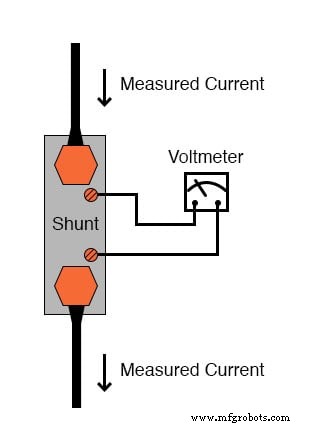
While using both an ammeter and a voltmeter introduces compound error—each instrument’s uncertainty adds to the final result—replacing the ammeter with a calibrated shunt resistor can reduce this error. A shunt typically has a resistance in the milliohm or microohm range, so its voltage drop is small but precisely measurable. When combined with a high‑impedance (potentiometric) voltmeter, the measurement accuracy can surpass that of the ammeter‑voltmeter pair.
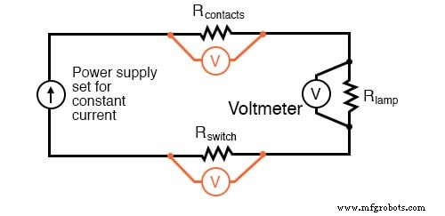
Below is an example of a Kelvin measurement circuit employing a shunt resistor for current measurement.
For optimal results, the current‑carrying leads should be bolded in diagrams to emphasize their role, and the voltage‑sensing leads should be shown as thin. In practice, a potentiometric voltmeter ensures minimal current flows through the sensing leads, further reducing stray voltage effects.
Practical Applications
The Kelvin method is invaluable for troubleshooting hidden or long‑run wiring. By supplying a constant current from a DC power source and measuring the voltage drop across specific points, you can detect unexpected resistances that indicate poor connections or damaged conductors. This technique works well for both powered circuits and unpowered AC conductors (ensure AC is de‑energized).
For example, measuring the voltage drop across a light switch can reveal whether the switch contacts or its wiring are compromised. Recording these baseline measurements on new circuits creates a reference that can accelerate future diagnostics.
RELATED WORKSHEETS
- Ohmmeter – Kelvin Worksheet
- Ammeter – Kelvin Worksheet
- DC Motor – Kelvin Worksheet
Industrial Technology
- Hands‑On Guide to Current Dividers: Build, Measure, and Simulate with a 6 V Battery
- Precision 4‑Wire Resistance Measurement: The Kelvin Method
- Understanding Electrical Resistance and Circuit Safety
- Ohm’s Law Explained: How Voltage, Current, and Resistance Interact in Electrical Circuits
- Resistors: Fundamentals, Types, and Practical Applications
- Understanding Ohm’s Law and the Real Risks of Electrical Shock
- Understanding Conductance: The Inverse of Resistance
- pH Measurement: Fundamentals, Electrodes, and Best Practices
- Calculating Wire Resistance for Voltage‑Drop‑Critical Circuits
- Understanding Resistance, Reactance, and Impedance in AC Circuits