


Understanding Resistance, Reactance, and Impedance in AC Circuits
Before delving into how resistors, inductors, and capacitors behave together in alternating‑current (AC) networks, let’s recap the core concepts.
Resistance
Resistance is the electrical friction that opposes current flow. It is inherent in all conductors—except ideal superconductors—and is most commonly expressed in dedicated resistive elements. When an AC signal traverses a resistor, the resulting voltage drop is in phase with the current. The symbol for resistance is R, and its unit is the ohm (Ω).
Reactance
Reactance represents the opposition that arises from changing electric or magnetic fields, analogous to inertia in mechanical systems. It is the hallmark of capacitors and inductors. For a purely reactive element, the voltage drop lags or leads the current by exactly 90°, depending on the component type. Reactance is denoted by X and measured in ohms (Ω).
Impedance
Impedance combines both resistance and reactance into a single complex quantity that describes the total opposition to AC flow. Every circuit element exhibits impedance, making it the natural parameter for AC analysis. When AC passes through an impedance, the voltage drop can be anywhere between 0° and 90° out of phase with the current. Impedance is symbolized by Z and expressed in ohms in its complex form.
Ideal resistors exhibit only resistance, while perfect inductors and capacitors show only reactance. Because all components ultimately possess impedance, it is standard practice to convert resistance, inductance, and capacitance values into impedance before analyzing an AC circuit.
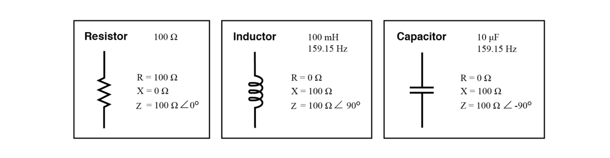 Perfect resistor, inductor, and capacitor.
The impedance phase angle of a component is the phase shift between its voltage and current. For a resistor, the angle is 0°, since voltage and current are always in phase. An inductor’s voltage leads current by +90°, giving it an angle of +90°. A capacitor’s voltage lags current by 90°, resulting in an angle of –90°.
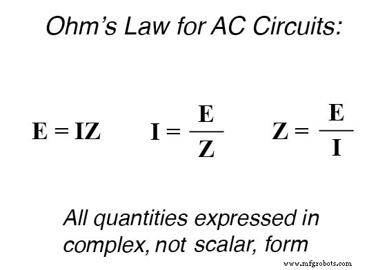
Impedances add in series and combine in parallel just as resistances do in DC circuits. The AC version of Ohm’s Law, expressed in terms of impedance, is illustrated below:
RELATED WORKSHEETS:
- Impedance Worksheet
- AC Power Worksheet
- Capacitive Reactance Worksheet
- Inductive Reactance Worksheet
Industrial Technology
- Precision 4‑Wire Resistance Measurement: The Kelvin Method
- Understanding Voltage and Current: The Foundations of Electrical Flow
- Understanding Electrical Resistance and Circuit Safety
- Ohm’s Law Explained: How Voltage, Current, and Resistance Interact in Electrical Circuits
- Understanding Ohm’s Law and the Real Risks of Electrical Shock
- Precision 4‑Wire Kelvin Resistance Measurement: Eliminating Wire‑Resistance Errors
- Capacitors & Calculus: How Voltage Change Drives Current
- Inductors & Calculus: How Current Change Drives Voltage
- Mastering Series RLC Circuit Analysis: From Impedance to KVL
- Understanding Characteristic Impedance in Transmission Lines