


Why Capacitors Beat Inductors: Lower Loss, Compact Size, and Superior Isolation
Like inductors, an ideal capacitor is a purely reactive element with no resistive, power‑dissipating component. In practice, however, capacitors tend to be far purer than inductors because their internal series resistance can be engineered to be very low.
As a result, the impedance phase angle of a real capacitor approaches –90° more closely than that of an equivalent inductor, leading to significantly reduced power loss.
Capacitors are also smaller and lighter than their inductor counterparts. Their electric fields are largely confined between the plates, whereas inductors generate magnetic fields that extend beyond the core, making capacitors less prone to coupling electromagnetic noise with adjacent circuitry.
These advantages make capacitors the preferred choice for designers whenever either component type is viable.
When a capacitor exhibits noticeable resistive effects, it is termed lossy. The primary source of loss is the dielectric material, not the conductors, since the conductor paths are minimal. Dielectrics react to changing electric fields by generating heat—a loss that appears as an effective resistance in the circuit.
This heating effect becomes more pronounced at higher frequencies and can even be exploited for dielectric heating processes, such as curing plastic films with high‑frequency AC applied between two metal plates.
To minimize dielectric loss, engineers select materials with lower loss characteristics. Below is a relative ranking of common dielectrics from least to most lossy:
Dielectric Loss
| Material | Loss |
|---|---|
| Vacuum | Low |
| Air | – |
| Polystyrene | – |
| Mica | – |
| Glass | – |
| Low‑K ceramic | – |
| Plastic film (Mylar) | – |
| Paper | – |
| High‑K ceramic | – |
| Aluminum oxide | – |
| Tantalum pentoxide | High |
Dielectric loss manifests as both a series resistance and a parallel resistance alongside the ideal capacitance:
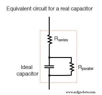
Real capacitors exhibit both series and parallel resistance.
Fortunately, these stray resistances are typically modest—low series resistance and high parallel resistance—making them far less impactful than the stray resistances found in most inductors.
RELATED WORKSHEETS:
- Conductors and Insulators Worksheet
Industrial Technology
- Mastering SPICE: Common Quirks & How to Avoid Them
- Capacitor Types: Polarized, Non-Polarized, and Variable Explained
- Peak Detector: How It Works and Practical Applications
- Common-Emitter Amplifier Limitations: Distortion, Temperature, and High‑Frequency Challenges
- Decoding JFET Quirks: Common Pitfalls & How to Master Them
- Common IGFET Quirks & How to Mitigate Them
- Understanding Capacitor Transient Response: Charging Dynamics, Asymptotic Behavior, and SPICE Simulation
- Real‑World Inductor Behavior: Skin Effect, Losses, and the Q Factor
- AC Capacitor Circuits: Capacitive Reactance, Phase Shift, and Power Behavior
- Electric Pendulum: How Capacitors and Inductors Exchange Energy