


Real‑World Inductor Behavior: Skin Effect, Losses, and the Q Factor
In an ideal world, an inductor would behave as a perfectly reactive component, offering only inductive reactance to AC. In practice, however, every inductor has measurable resistance, and its performance is influenced by several frequency‑dependent loss mechanisms.
Because an inductor is built from wire, the conductor’s inherent resistance is effectively in series with the coil’s ideal inductance:
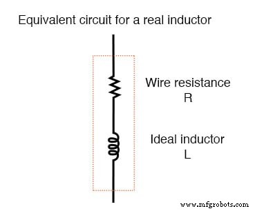
Equivalent circuit of a real inductor.
Consequently, the impedance of any real inductor is always a complex mix of resistance and inductive reactance.
Two major contributors to this resistance are the skin effect and electromagnetic radiation. The skin effect causes AC current to flow predominantly near the surface of the conductor, reducing the effective cross‑sectional area and increasing resistance as frequency rises. In contrast, DC current uses the full cross‑section, so skin effect is irrelevant in DC circuits.
At high frequencies, the alternating magnetic field of an inductor can radiate energy into space as an electromagnetic wave. This radiated power never returns to the coil and appears as additional loss in the circuit.
Eddy Currents in Iron‑Core Inductors
When an AC voltage is applied to an iron‑core inductor, the changing magnetic field induces circulating currents—eddy currents—within the core. Because iron is a poor electrical conductor compared to copper, these currents dissipate energy as heat, adding to the effective resistance.
Eddy currents are mitigated by laminating the core: thin, insulated sheets are stacked together, preventing large loops and thus reducing losses. This technique is essential in high‑frequency applications where eddy‑current heating would otherwise dominate.
In some industries, the very same effect is harnessed for inductive heating, enabling non‑contact, high‑purity heating in vacuum or sealed environments.
For conductors, eddy currents can also form within the wire’s cross‑section at high frequencies. Litz wire—an assembly of many fine, insulated strands—helps suppress this phenomenon by forcing current to distribute more uniformly.
Magnetic hysteresis also contributes to losses. Each time the core’s magnetic field reverses, energy is expended overcoming the material’s coercivity. Ferrite cores, while low in core loss at high frequencies, exhibit significant hysteresis, so careful material selection and limiting peak flux density are critical for minimizing resistance.
All these non‑idealities—wire resistance, skin effect, radiation, eddy currents, and hysteresis—are collectively represented by the effective resistance of a real inductor.
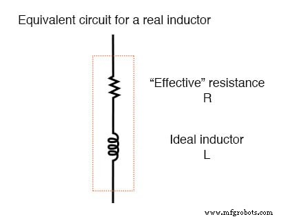
Equivalent circuit of a real inductor with skin‑effect, radiation, eddy‑current, and hysteresis losses.
It’s worth noting that skin effect and radiation losses also affect straight lengths of wire in AC circuits, becoming especially noticeable at radio frequencies. A radio transmitter’s antenna, for instance, is deliberately designed to maximize electromagnetic radiation.
Quality Factor (Q Factor)
The Q factor is a convenient way to quantify how “pure” an inductor is. It is defined as the ratio of inductive reactance to effective resistance:
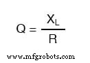
A higher Q indicates lower loss and a more ideal inductor. While inductive reactance increases with frequency, effective resistance also varies with frequency, so the Q value must be specified at a particular test frequency to have practical meaning.
In AC circuit design, choosing an inductor with a high Q is preferable because it ensures that the device behaves as close as possible to the ideal case, minimizing undesired energy dissipation.
RELATED WORKSHEETS:
- Inductors Worksheet
Industrial Technology
- Hands‑On Electromagnetism Experiment: Build and Test a Simple Electromagnet
- Mastering SPICE: Common Quirks & How to Avoid Them
- Inductors Explained: Types, Functions, and Applications
- Understanding Ladder Diagrams: Design, Wiring, and Safety in Industrial Control Systems
- Common-Emitter Amplifier Limitations: Distortion, Temperature, and High‑Frequency Challenges
- Decoding JFET Quirks: Common Pitfalls & How to Master Them
- Common IGFET Quirks & How to Mitigate Them
- Understanding Conductor Ampacity: How Wire Size, Insulation, and Standards Determine Current Capacity
- Why Capacitors Beat Inductors: Lower Loss, Compact Size, and Superior Isolation
- Barbed Wire Explained: History, Construction, and Modern Uses