


Understanding Ladder Diagrams: Design, Wiring, and Safety in Industrial Control Systems
Ladder diagrams—commonly referred to as ladder logic—are the industry-standard schematics used to illustrate electromechanical control circuits. They resemble a ladder because each diagram features two vertical rails (the power supply) and one or more horizontal rungs representing individual control branches.
For example, a simple diagram that shows a lamp operated by a hand switch looks like this:
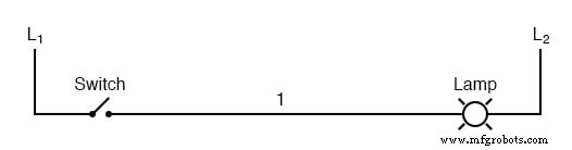
The labels L1 and L2 identify the two poles of a 120 V AC supply. L1 is the hot conductor, and L2 is the neutral (grounded) conductor. These designations are purely symbolic and have nothing to do with inductors. In a real installation, the transformer or generator would feed the circuit, but that component is omitted here for clarity.
In practice, the circuit would resemble this:
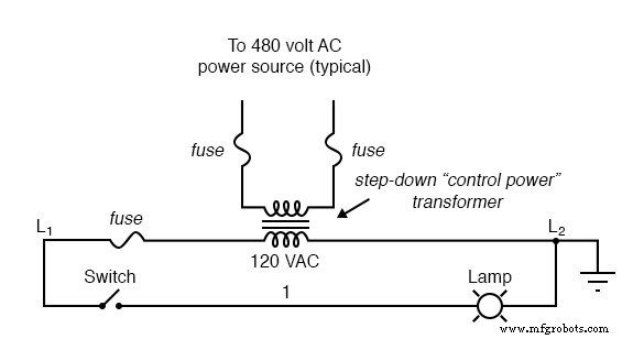
Industrial relay logic typically runs on 120 V AC, though lower‑voltage AC or DC systems are also documented with the same ladder‑diagram conventions:
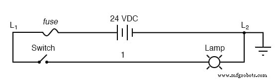
As long as the switch contacts and relay coils are properly rated, the chosen voltage level does not impact the diagram’s structure.
Importance of Wire Numbers in a Circuit
Notice the number “1” on the wire connecting the switch to the lamp. In the field, that conductor would carry a wire‑number tag—typically a heat‑shrink or adhesive label—so it can be quickly identified during assembly or maintenance.
Wires that feed the switch would be labeled L1 and 1, while those that lead to the lamp would be labeled 1 and L2. Assigning a unique, consistent number to every electrically common point simplifies troubleshooting and reduces installation errors.
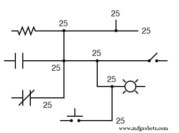
Wire numbers never change at junctions or nodes, even if the conductor’s size, color, or length varies. Consistent labeling ensures that a single, continuous point in the control circuit always shares the same identifier.
For example, wire #25 may run through several devices but remains a single electrically continuous path:
Placement of Elements in a Ladder Diagram
In ladder diagrams, the load (lamp, relay coil, solenoid, etc.) is almost always drawn on the right side of the rung. While the coil’s electrical position within the rung is flexible, the grounding of the power rail is critical for reliable operation.
Consider this example:
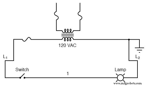
Here, the lamp sits on the right, and the ground connection follows the same side of the power rail. This deliberate placement prevents accidental shorting and protects the circuit.
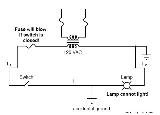
If wire #1 were to touch a grounded metal conduit—perhaps because its insulation wore away—the circuit would short both sides of the lamp, rendering it inoperable. The switch closing would then trigger a fuse blow:
Reversing the switch and fuse positions while still grounding L2 changes the outcome. In this configuration, the accidental grounding of wire #1 energizes the lamp regardless of the switch state, potentially leading to uncontrolled operation.
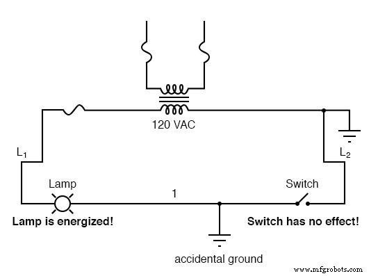
Designing the ladder so that loads sit nearest the grounded rail ensures that a fault will blow a fuse rather than cause unintended energization. This is a fundamental safety principle in industrial control design.
Key Takeaways
- Ladder diagrams use two vertical rails (L1 = hot, L2 = neutral) and horizontal rungs for each control branch.
- Consistent wire numbering (or lettering) across all electrically common points is essential for clarity and safety.
- Loads should be positioned nearest the grounded power rail to guarantee that a short‑fault will trip a protective device instead of energizing the load.
- These diagrams are versatile and can represent both AC and DC control systems, provided all components are appropriately rated.
Related Worksheets
- Electromechanical Relay Logic Worksheet
- AC Motor Control Circuits Worksheet
Industrial Technology
- Hands‑On Electromagnetism Experiment: Build and Test a Simple Electromagnet
- Switches, Electrically Actuated (Relays): The Ladder Logic Legacy
- Understanding Conductor Ampacity: How Wire Size, Insulation, and Standards Determine Current Capacity
- Real‑World Inductor Behavior: Skin Effect, Losses, and the Q Factor
- Barbed Wire Explained: History, Construction, and Modern Uses
- Comprehensive Electrical Wiring Installation Guides & Diagrams
- Installing a GFCI Outlet: Step‑by‑Step Wiring Guide & Circuit Diagrams
- Professional Wiring Guide for Combo Switch/Outlet Devices – Diagrams & Installation Tips
- Step‑by‑Step Guide: Wiring a Household Outlet Receptacle with Clear Diagrams
- Step‑by‑Step Guide: Wiring an AFCI Combo Switch with Diagrams