


Switches, Electrically Actuated (Relays): The Ladder Logic Legacy
At the heart of every programmable logic controller (PLC) is ladder logic – a programming paradigm that traces its roots back to the electrical ladder diagrams that once guided relay panels in industrial automation.
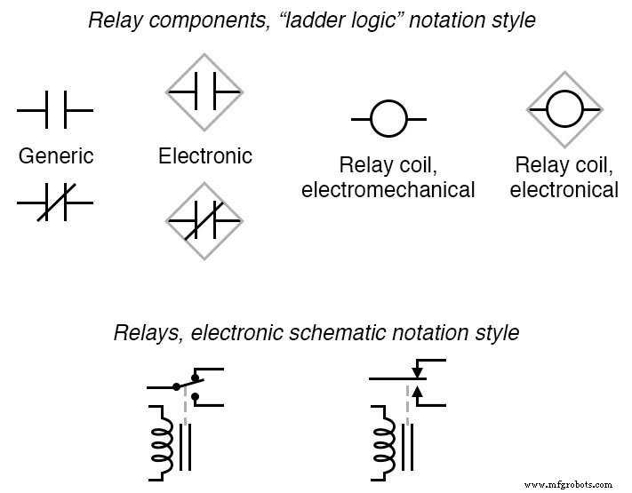
These diagrams were meticulously drawn to show how coils, contacts, and other devices were interconnected. They earned the nickname “ladder diagrams” because their structure mirrors a ladder: two vertical rails (the power rails) and horizontal rungs (the circuit connections) that span between them.
Understanding this heritage is more than a historical exercise; it gives engineers a visual language that bridges legacy relay-based systems and modern digital control. It also clarifies why ladder logic remains intuitive for technicians trained on relay panels.
For those looking to deepen their grasp of relay fundamentals, we recommend the following worksheet:
By mastering these concepts, you’ll be equipped to design, troubleshoot, and maintain both traditional relay systems and contemporary PLC programs with confidence.
Industrial Technology
- Hand‑Actuated Switches: Types, Symbols, and Applications
- Process‑Actuated Switches: How They Work and When They Change State
- Understanding Electrical Switches: Types, Functions, and Applications
- Understanding Time-Delay Relays: Types, Applications, and Advanced Features
- Protective Relays: Safeguarding Industrial Power Systems
- Solid‑State Relays: Advantages, Limitations, and Practical Insights
- Understanding Ladder Diagrams: Design, Wiring, and Safety in Industrial Control Systems
- Understanding Boolean Relationships Using Venn Diagrams
- Wire Two Switches in Parallel to Control a Single Light
- Ensuring Reliability: Potting Techniques and Flat Ribbon Sealing in Switches & Relays