


Understanding Digital Logic Functions: OR, AND, NOT, and Beyond
In this article we explore how a basic ladder diagram can represent fundamental digital logic operations. By arranging contacts in series, parallel, and using normally‑closed (NC) contacts, we can implement OR, AND, NOT, NAND, NOR, and even XOR functions with a simple lamp as the output device.
Creating an OR Function
Using two normally‑open (NO) contacts in parallel, the lamp lights when either switch A or switch B is closed. The truth table is shown below:
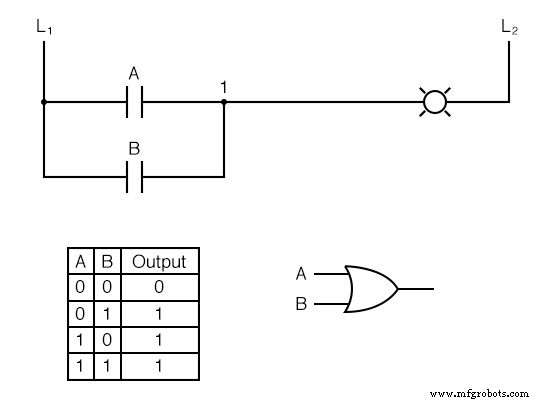
This is a classic OR gate: a single path from wire L1 to the lamp suffices.
Building an AND Function
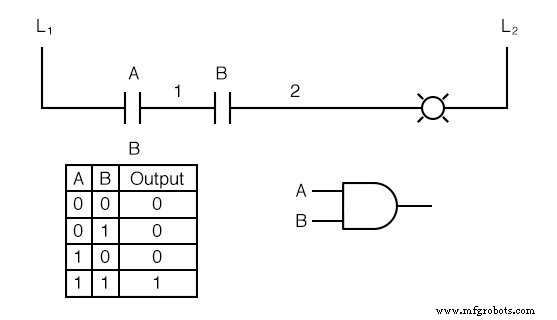
Placing the same contacts in series yields an AND gate. The lamp energizes only when both contacts are closed, creating a continuous path from L1 to the lamp.
Implementing NOT with Normally‑Closed Contacts
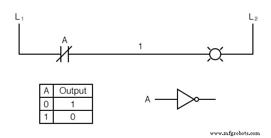
By replacing an NO contact with an NC contact, the lamp reacts to the inverse state: it lights when the contact is open and de‑energizes when the contact closes.
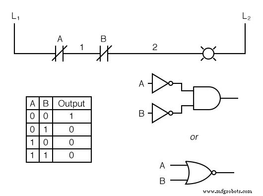
Deriving NAND and NOR via De Morgan’s Theorem
Inverting the inputs of an OR gate (using NC contacts) produces a NAND gate. The lamp illuminates if either input is unactuated and turns off only when both are actuated.
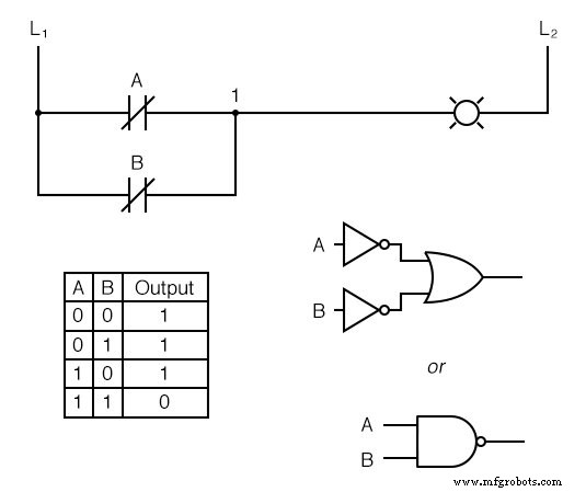
Similarly, inverting the inputs of an AND gate yields a NOR gate.
Mapping Ladder Contacts to Logic Gates
- Parallel contacts = OR gate
- Series contacts = AND gate
- Normally‑closed contacts = NOT gate (inverter)
Constructing an Exclusive‑OR (XOR) Function
An XOR gate can be built by combining AND, OR, and NOT gates. The ladder diagram below demonstrates this construction:
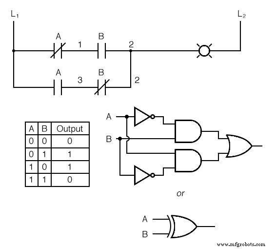
The top rung (NC A in series with NO B) implements a NOT/AND combination, while the bottom rung (NO A in series with NC B) does the same with reversed inputs. Parallel connection of these rungs (wire 2) provides the OR operation that powers the lamp.
Designing the XOR Circuit
Each input requires two contacts: one direct and one inverted. The contacts share a common label (e.g., “A”) to indicate they are actuated by the same switch or relay. If more detailed distinction is needed, compound labels such as “A‑1” and “A‑2” can be used.
When the output of any logic function needs to be inverted, a relay with an NC contact is employed. For example, to drive a lamp based on the NOT of a normally‑open contact, we can use the following ladder:
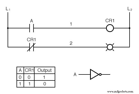
Here, the coil of CR1 energizes the lamp, and its NC contact opens when CR1 is energized, providing the inversion.
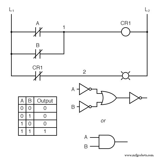
Applying this strategy to a NAND function transforms it into an AND function, as illustrated below:
Review Summary
- Parallel contacts = OR gate
- Series contacts = AND gate
- Normally‑closed contacts = NOT gate
- Relays with NC contacts invert the output of a logic gate; simple NC contacts invert inputs.
Related Worksheets
- Boolean Algebra Worksheet
- Electromechanical Relay Logic Worksheet
- Digital Logic Signals Worksheet
Industrial Technology
- Why Tungsten Contacts Power Reliable Electrical Appliances
- Designing Reliable Switch Contacts: Materials, Types, and Protection Strategies
- Eliminating Contact Bounce in Mechanical Switches
- Combinational Logic Functions: Fundamentals & Practical Applications
- Digital Logic with Feedback: From Deterministic Gates to Multivibrators
- Optimizing Ohmic Contacts on p‑GaAs Nanowires for Low‑Resistance, High‑Reliability Devices
- Digital Logic Board Kit: Components & Setup Guide
- Key Factors in Designing Contactor Contacts
- Digital Logic Gates Explained: Types, Functions & Applications
- Digital Integrated Circuits: Types & Applications