


Digital Logic Board Kit: Components & Setup Guide
Components and supplies
 |
| × | 2 | |||
 |
| × | 100 | |||
 |
| × | 52 | |||
|
| × | 40 | |||
 |
| × | 40 | |||
 |
| × | 52 | |||
 |
| × | 2 | |||
 |
| × | 1 | |||
 |
| × | 1 | |||
|
| × | 1 | |||
 |
| × | 1 | |||
 |
| × | 1 |
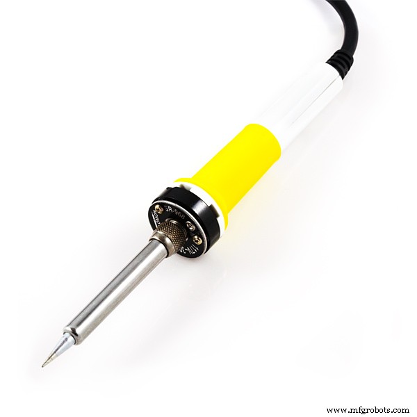
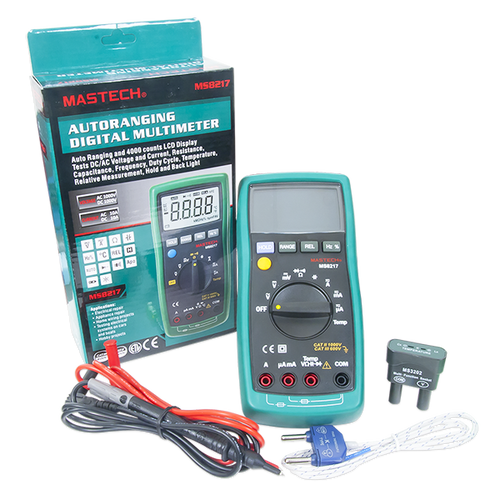
Necessary tools and machines
 |
| |||
 |
| |||
 |
|
Apps and online services
 |
|
About this project
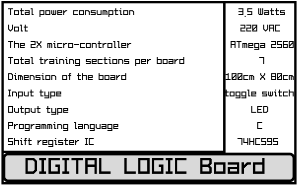
AbstractThis tutorial is designed specially for “Digital Logic Board," classified as intermediate level difficulty design, used as a training device for practicing purpose, for new beginner in electronics world, including concepts of important circuit in the electronic logic circuit.
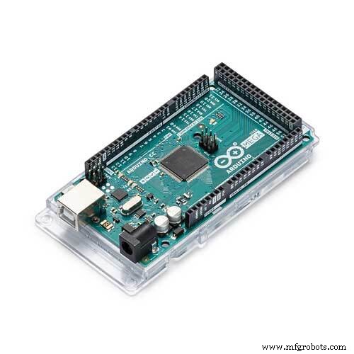
Instead of old TTL “transistor-transistor logic” circuit, we use a Microchip microcontroller, that can programmed by using Arduino prototype board and the Arduino IDE.
The main topics of this project is learning logics and the protocol timing and transferring data, and all of it deal with digital Boolean signals.
In next pages, we explain a lot of concept about this project:
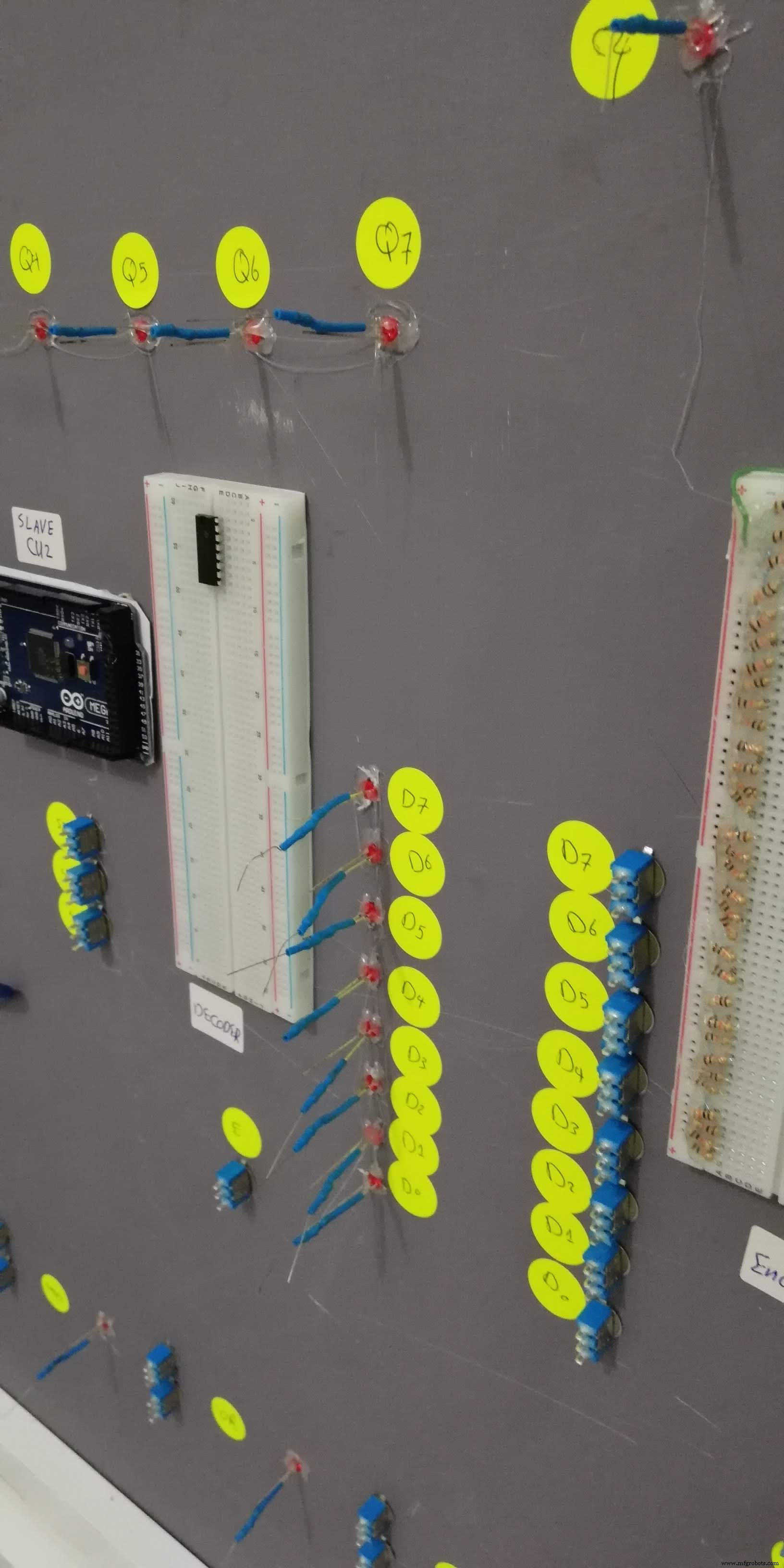
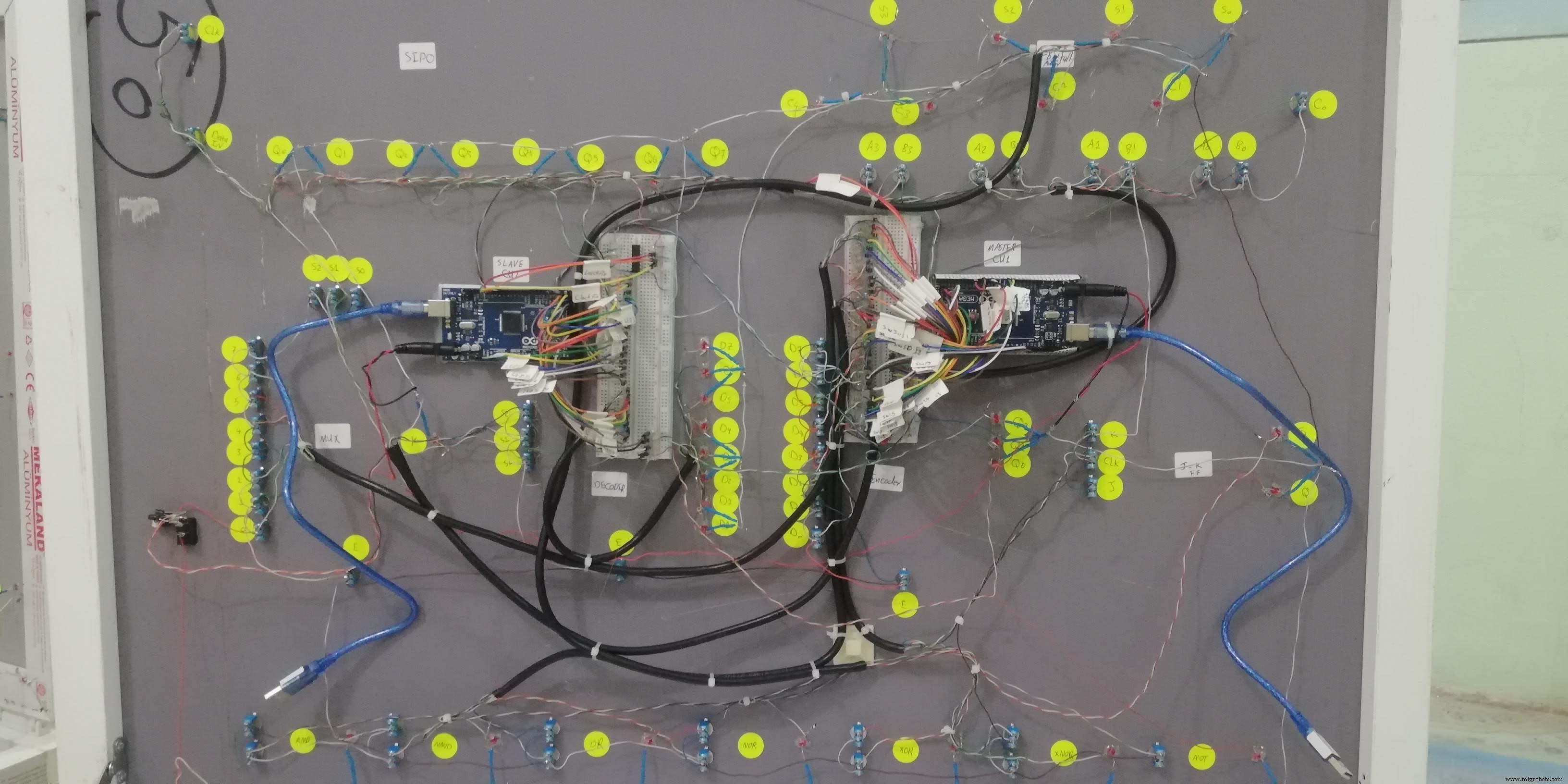
- The slave Arduino board at the left power up the LED by using a 4-byte data frame that send by Master Arduino and control 74HC595 IC directly.
- The 2-wire SDA and SCL synchronise the byte stream between two Arduino by using I2C protocol.
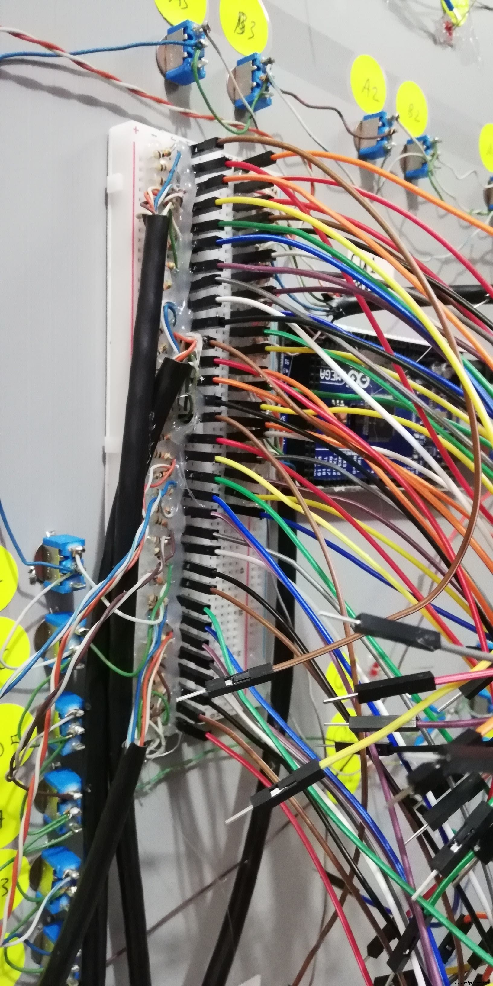
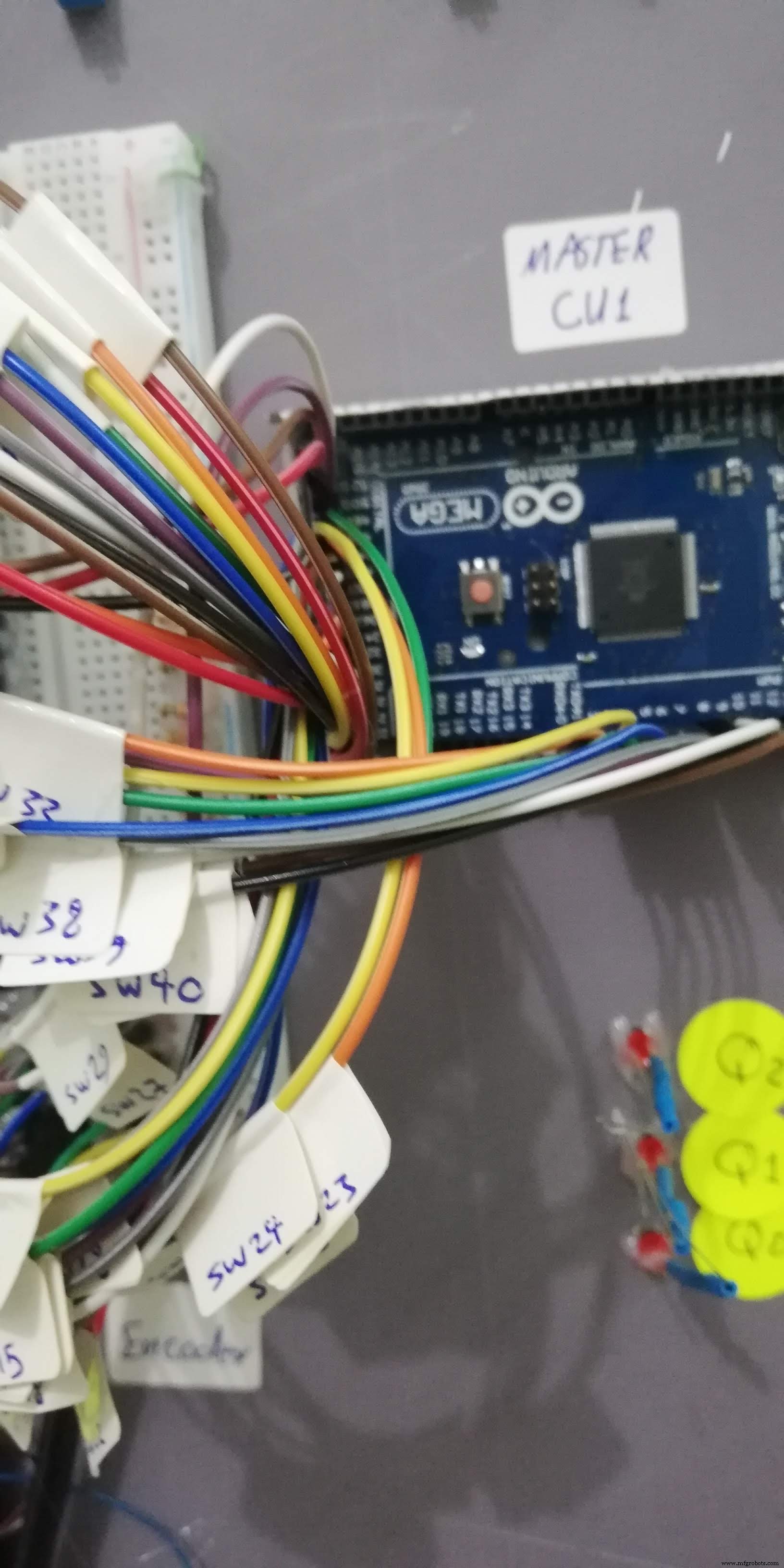
- The main Arduino board at the right read the switches states and decide to send a single bit through a I2C Bus with 4-byte frame data message.
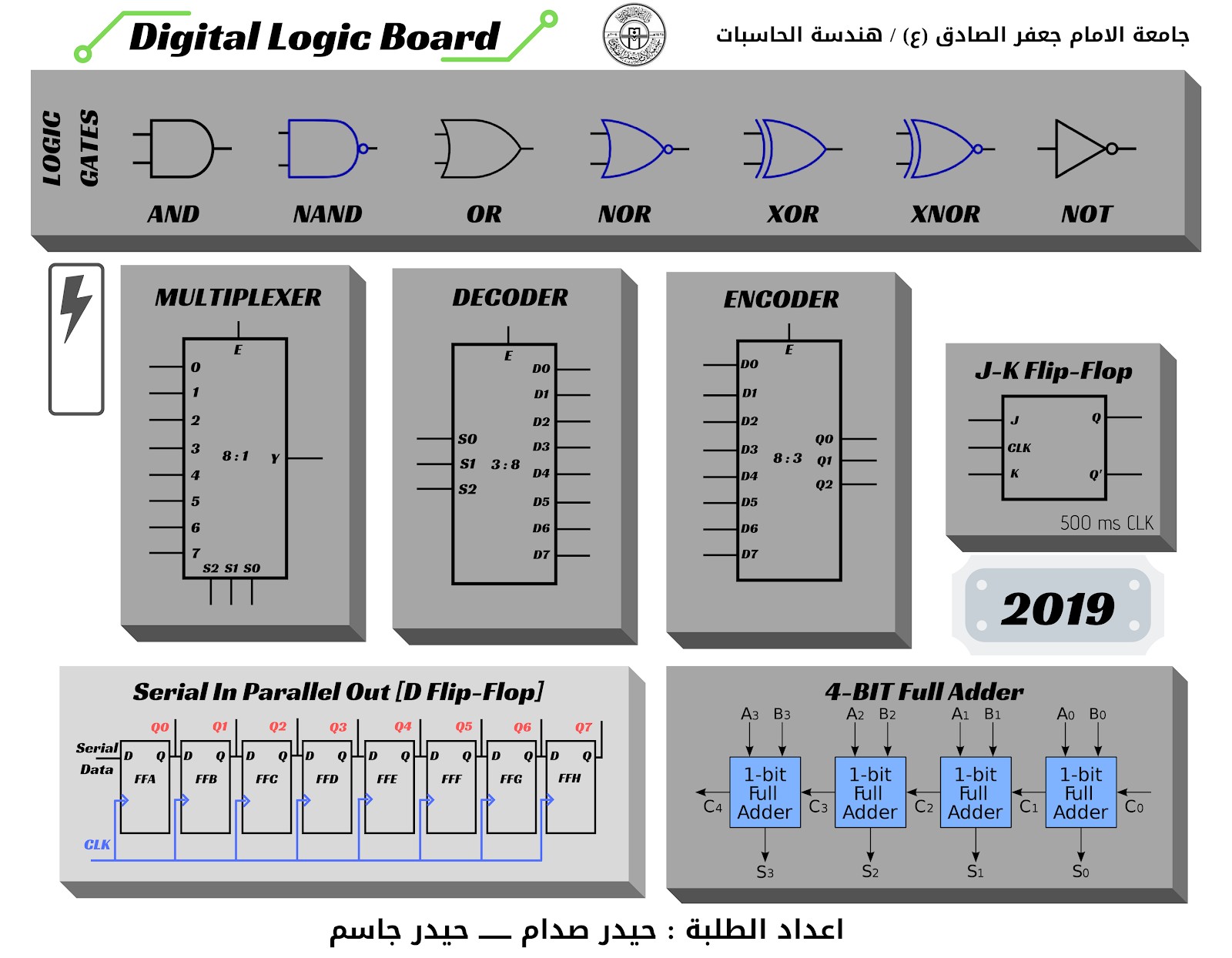
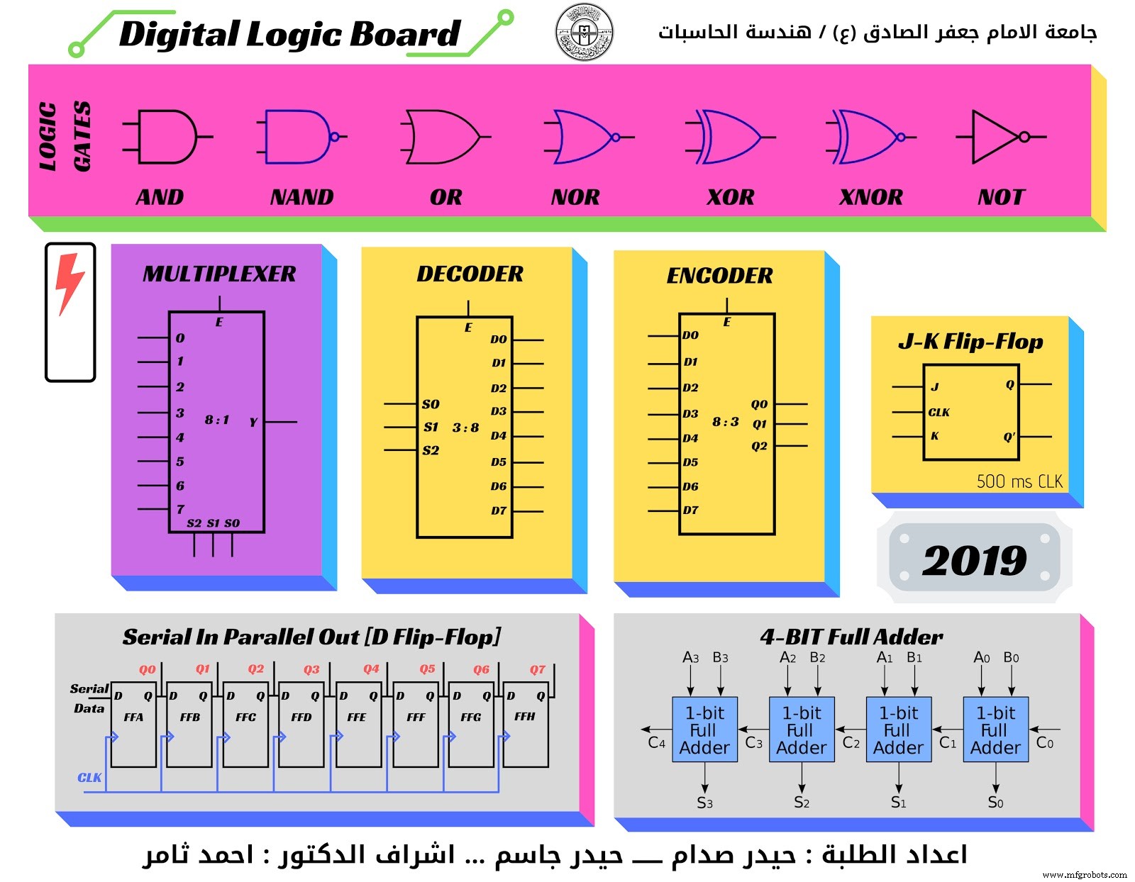
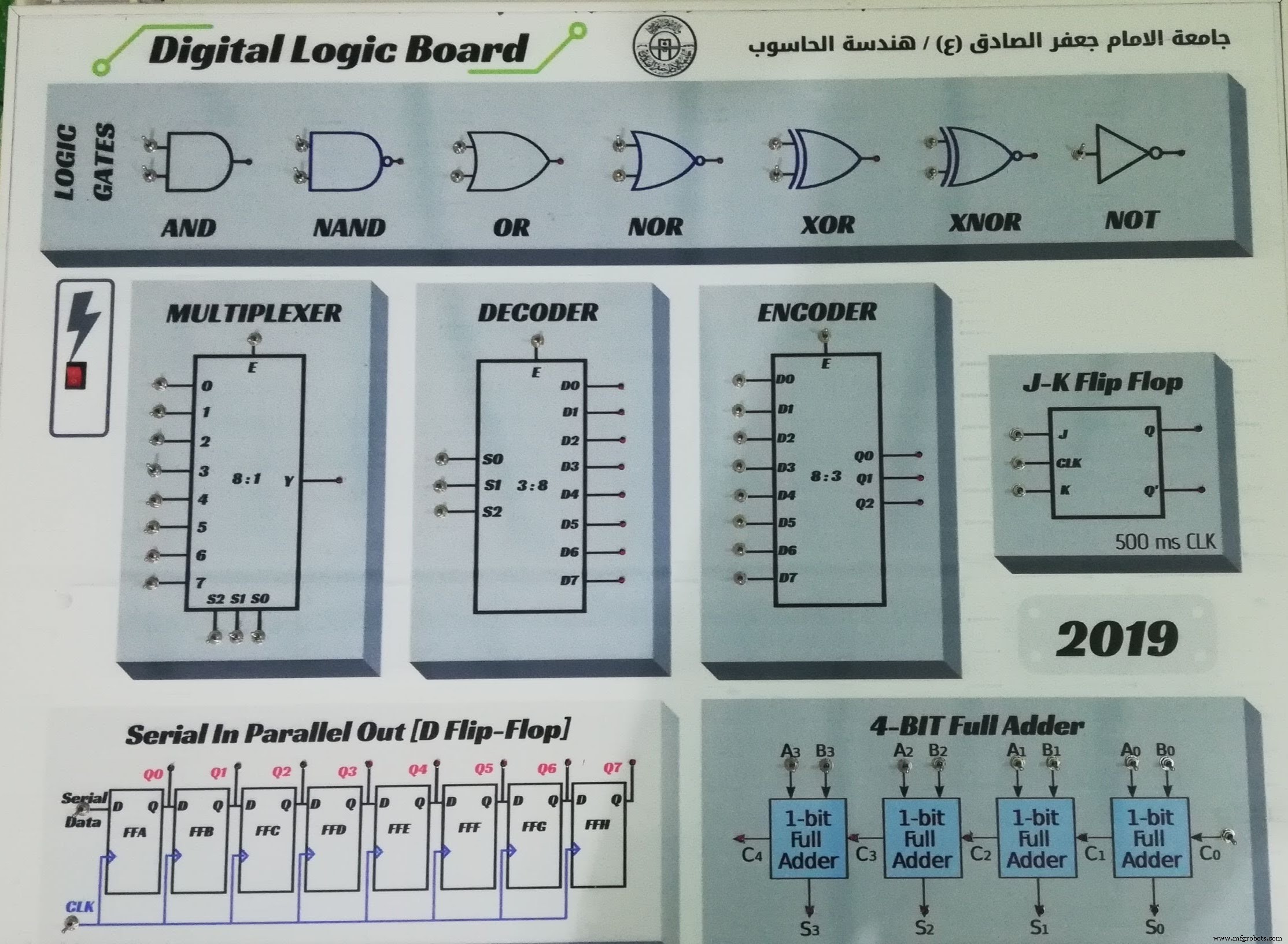
From Top to Down Arrow
- 7 Logic Gates
- DC Power Switch
- 8-bit Multiplexer
- 8-bit Decoder
- 8-bit Encoder
- J-K Flip Flop
- SIPO shift register
- 4-Bit full adder
- Student name
Canva is a graphic design tool website, founded in 2012. It uses a drag-and-drop format and provides access to over a million photographs, graphics, and fonts.It is used by non-designers as well as professionals. The tools can be used for both web and print media design and graphics.

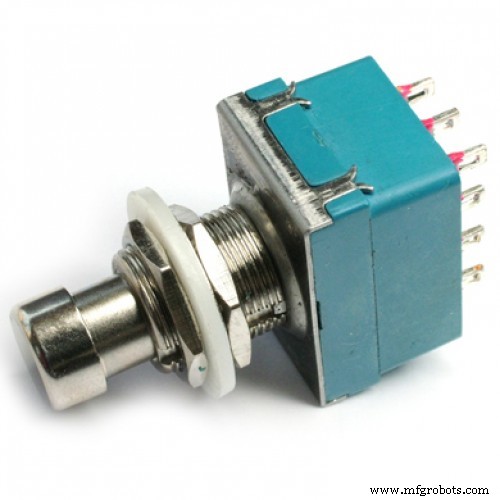
- First of all you need to power up the board by using Rocker Switch
- To make change for input logic move the Toggle Switch
- If logic is true then the RED LED will illuminate
- In this case you need to learn the Truth Table of every single circuit
- The Logic Gates is (AND, NAND, OR, NOR, XOR, XNOR, NOT)
- Multiplexer
- Decoder, Encoder
- J-K Flip Flop
- Shift Register
- 4-Bit Full Adder
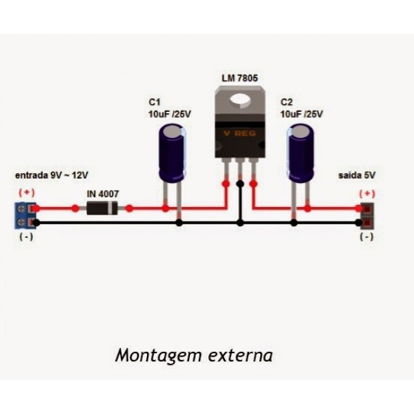
This device may take a 1.5 Volt as a drove voltage so you must supply it with minimum 8 volt or more for power hungry purpose.
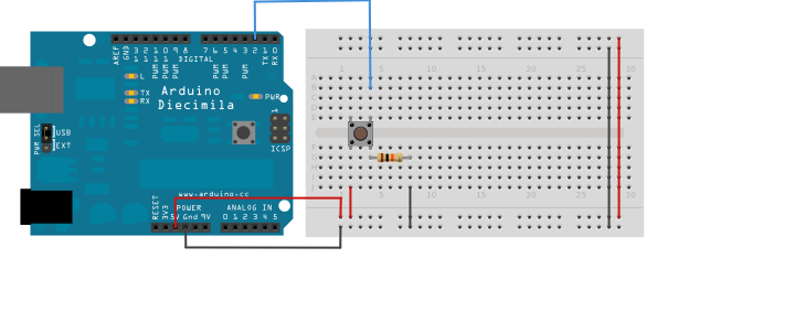
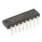
1. Make the following connections:
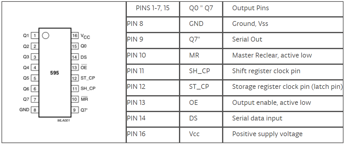
GND (pin 8) to ground,
Vcc (pin 16) to 5V
OE (pin 13) to ground
MR (pin 10) to 5V
This set up makes all of the output pins active and addressable all the time. The one flaw of this setup is that you end up with the lights turning on to their last state or something arbitrary every time you first power up the circuit before the program starts to run. You can get around this by controlling the MR and OE pins from your Arduino board too, but this way will work and leave you with more open pins.
2. Connect to Arduino
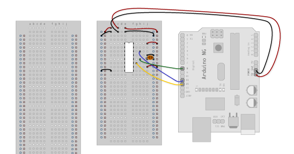
DS (pin 14) to Ardunio DigitalPin 11 (blue wire)
SH_CP (pin 11) to to Ardunio DigitalPin 12 (yellow wire)
ST_CP (pin 12) to Ardunio DigitalPin 8 (green wire)
From now on those will be referred to as the dataPin, the clockPin and the latchPin respectively.
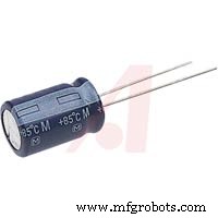
Notice the 0.1"f capacitor on the latchPin, if you have some flicker when the latch pin pulses you can use a capacitor to even it out.
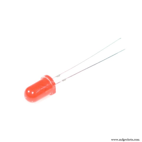
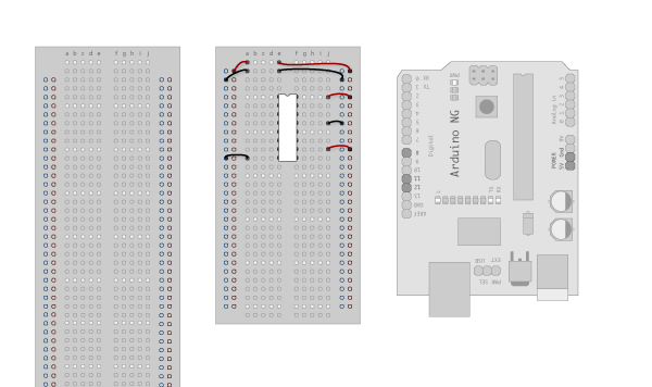
3. Add 8 LEDs
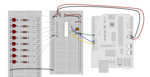
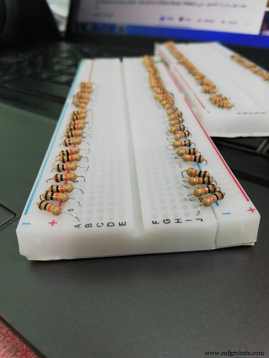
In this case you should connect the cathode (short pin) of each LED to a common ground, and the anode (long pin) of each LED to its respective shift register output pin. Using the shift register to supply power like this is called sourcing current. Some shift registers can't source current, they can only do what is called sinking current. If you have one of those it means you will have to flip the direction of the LEDs, putting the anodes directly to power and the cathodes (ground pins) to the shift register outputs. You should check the your specific datasheet if you aren't using a 595 series chip. Don't forget to add a 470-ohm resistor in series to protect the LEDs from being overloaded.
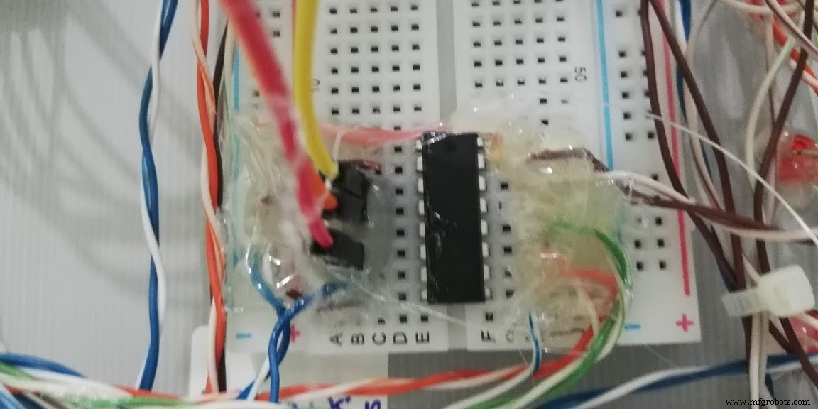
Our 74HC595 Design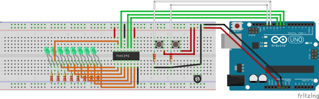
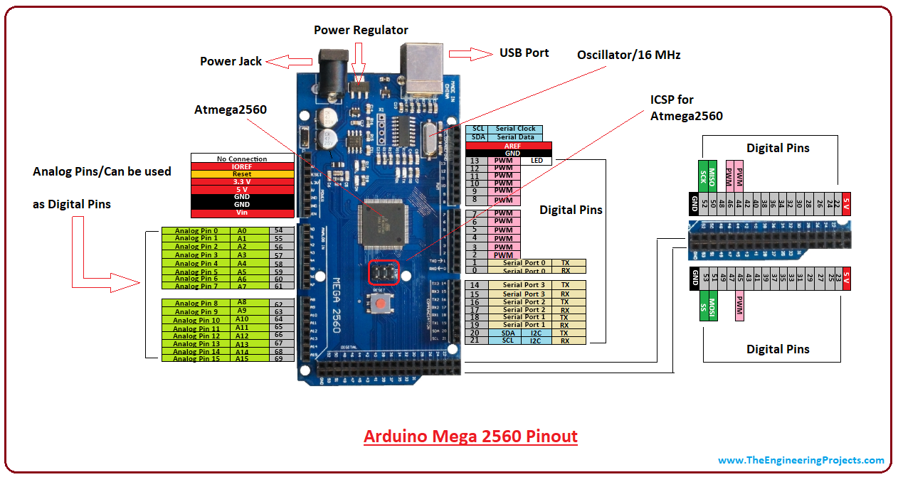
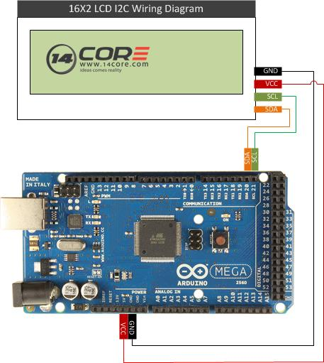
Serial Data Line (SDA) and Serial Clock Line (SCL) on Ateml Mega Arduino board
- SDA (Pin 20)
- SCL (Pin 21)
Code
Digital Logic Board GitHub
CU1 & CU2 softwarehttps://github.com/saifalikabi/Digital-Logic-BoardSchematics
Excel table for 2 mega controllerExcel table for 2 mega controllerManufacturing process
- Understanding Digital Logic Functions: OR, AND, NOT, and Beyond
- Digital Logic with Feedback: From Deterministic Gates to Multivibrators
- Ironing Board Manufacturing: Design, Materials, and Production Process
- Arduino Digital Dice Project: Build Your Own LCD-based Random Number Generator
- Build a Simple Obstacle Sensor with Arduino – Easy IR LED & Photodiode Tutorial
- Build an AI LCD Companion: Your Interactive Buddy
- Arduino MKR1000 WiFi Pick‑to‑Light System – Project 2
- Build a Reliable LCD Stopwatch with Arduino Nano – No Potentiometer Needed
- Hysteresis-Based Arduino Temperature Control System
- Ultrasonic Eyes: Interactive 8x8 LED Matrix Distance Sensor