


Permissive and Interlock Circuits in Industrial Control Systems
A practical application of switch and relay logic is in control systems where several process conditions must be met before a piece of equipment is allowed to start.
One common example is the burner control system for large combustion furnaces. To start the burners safely, the control logic must receive “permission” from multiple process switches: high and low fuel pressure, air fan flow, exhaust stack damper position, access door position, and more.
Each process condition is called a permissive. The permissive contacts are wired in series so that if any one detects an unsafe condition, the circuit opens.
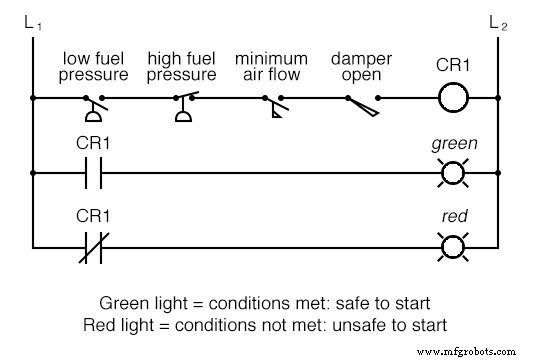
If all permissive conditions are satisfied, CR1 energizes and the green lamp illuminates. In a production system, a control relay or fuel‑valve solenoid would be placed in that rung, activating only when all permissive contacts are closed.
If any condition fails, the series string opens, CR2 de‑energizes, and the red lamp lights.
Note that the high‑fuel‑pressure switch is normally closed: it opens when pressure exceeds the setpoint. Since the normal state of a pressure switch is zero (low) pressure, we choose a normally‑closed device to trigger on excess pressure.
Relay Logic in Control Systems
Relay logic also ensures that two mutually exclusive events cannot occur simultaneously. A typical case is reversible motor control, where two contactors switch the motor’s phase sequence. Energizing both forward and reverse contactors simultaneously could short‑cycle phases A and B.
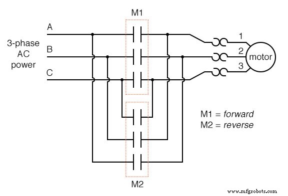
With contactor M1, phases A, B, and C connect directly to motor terminals 1, 2, and 3. With contactor M2, phases A and B are swapped, reversing the motor’s rotation.
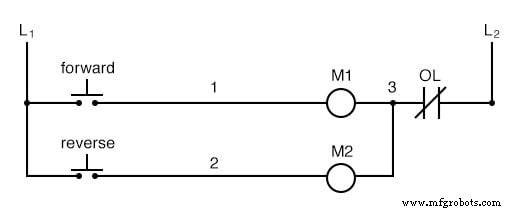
The diagram also shows a normally‑closed “OL” thermal‑overload contact on each phase. If a heater element overheats, the contact opens and blocks energization of both contactors.
This design works only if the operator never presses both buttons at once. Simultaneous actuation would short‑cycle phases A and B, creating a hazardous condition.
Preventing Short‑Circuits with Interlocks
To eliminate this risk, the circuit can be wired so that energizing one contactor automatically disables the other. This is called interlocking and is typically achieved with auxiliary contacts:
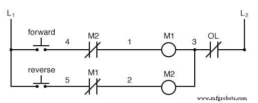
When M1 energizes, its normally‑closed auxiliary contact opens, preventing M2 from energizing even if the reverse button is pressed. The reverse is true when M2 is energized.
Some contactors include a mechanical interlock—a lever that physically prevents both armatures from closing together. For added safety, electrical interlocks can be combined with mechanical ones, and the simplicity of the circuit makes this practice standard in industry.
Review:
- Switch contacts that interrupt a circuit when certain physical conditions are not met are called permissive contacts; the system requires their “permission” to activate.
- Switch contacts that prevent a control system from executing two incompatible actions simultaneously are called interlocks.
Related Worksheets:
- Time‑Delay Electromechanical Relays Worksheet
Industrial Technology
- Verified SPICE Netlists & Example Circuits
- Advanced Motor Control Circuits: Latching, Stop, and Time‑Delay Techniques
- Passive Averager and Op‑Amp Summer Circuits: From Averaging to Addition
- Understanding Differentiator and Integrator Op‑Amp Circuits
- Control Circuits: Fundamentals, Applications, and Best Practices
- Understanding Power in Resistive and Reactive AC Circuits
- Mastering Raspberry Pi Sensor & Actuator Control: Accelerometer, Servo, and Data Streaming
- Master Stepper Motor Control with Arduino & A4988 Driver – Step-by-Step Guide
- How Brushless DC Motors and ESCs Operate – A Technical Overview
- Reliable Power & HVAC Rentals for Seamless Climate Control