


Understanding Power in Resistive and Reactive AC Circuits
In a single‑phase 120‑V, 60‑Hz AC system, a purely resistive load draws 2 A (RMS) and dissipates 240 W. Because the load has no reactance, the voltage and current waveforms are in phase, and the power waveform is always positive.
Below is a schematic of the basic resistive circuit:
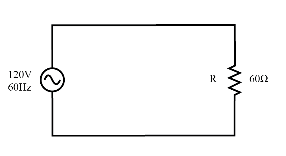
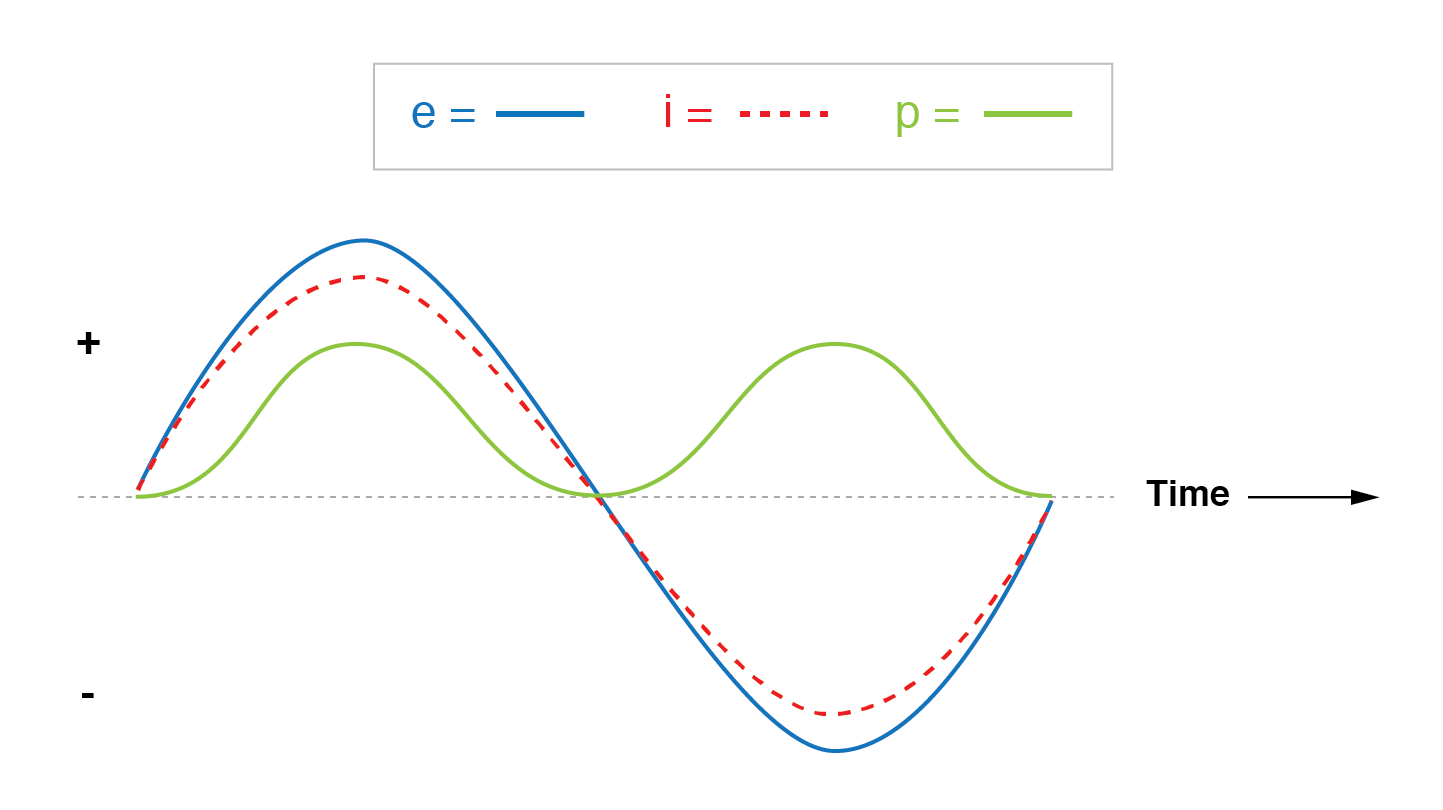
When you plot voltage, current, and instantaneous power, the voltage and current curves overlap, while the power curve sits entirely above the zero line, reflecting continuous energy dissipation. The power waveform oscillates at twice the frequency of the voltage or current because power is the product of the two.
Purely Reactive Loads
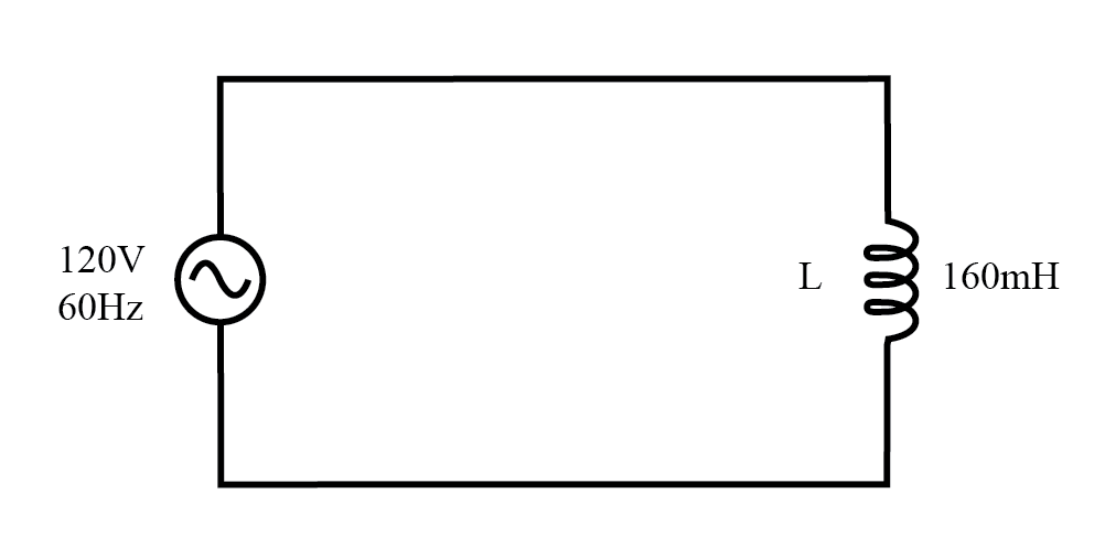
A circuit with only an inductor (or capacitor) behaves differently. The voltage leads the current by 90°, and the instantaneous power swings above and below zero, meaning the energy is alternately absorbed from and returned to the source. Net energy transfer over a cycle is zero.
Typical schematic:
Mixed Resistive‑Reactive Loads
When resistance and inductance coexist, the impedance is complex:
- Resistance, R = 60 Ω
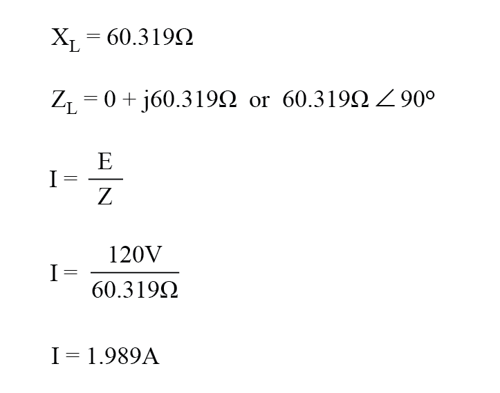
- Inductive reactance, XL = 2πfL = 2π·60·0.160 = 60.319 Ω
- Impedance, Z = R + jXL = 60 + j60.319 Ω ≈ 85.078 Ω ∠ 45.152°
With a 120‑V RMS supply, the RMS current is:
$$ I = \frac{V}{|Z|} = \frac{120\,\text{V}}{85.078\,\Omega} \approx 1.41\,\text{A} $$
The inductor itself does not dissipate real power; it merely stores and returns energy. The resistor dissipates the real portion of the power, so the load consumes more energy than it returns.
Illustrative waveforms:
Notice the power waveform spends more time above the zero line than below, confirming net energy absorption.
Key Takeaways
- Resistive only: Voltage and current are in phase; all power is dissipated as heat.
- Reactive only: Voltage and current are 90° out of phase; no net power is dissipated.
- Mixed: Phase angle between 0° and 90°; some power is stored/returned by reactance, while the resistor dissipates the remainder.
Because the instantaneous power wave has a different frequency and phase behavior than voltage or current, it is most accurate to compute power using scalar magnitudes of voltage, current, resistance, and reactance rather than complex algebra.
Related Worksheet: AC Power Worksheet
Industrial Technology
- Understanding AC Circuits: A Beginner's Guide
- Digital Integrated Circuits: Foundations and Best Practices
- Verified SPICE Netlists & Example Circuits
- Rectifier Circuits: From Half‑Wave to Polyphase Full‑Wave Designs
- Passive Averager and Op‑Amp Summer Circuits: From Averaging to Addition
- Power Supply Circuits: Types, Design Principles, and Performance
- Understanding Power in Electric Circuits: Measurement & Significance
- True, Reactive, and Apparent Power
- Practical Guide to Power Factor Correction in AC Systems
- Understanding Reactive Power: Key Insights for Power System Reliability