


True, Reactive, and Apparent Power
Reactive Power
In alternating‑current circuits, inductors and capacitors do not dissipate energy—they merely store and release it. Yet because they draw current while dropping voltage, they can appear to consume power. This apparent consumption is known as reactive power and is quantified in Volt‑Amps Reactive (VAR), not watts.
The standard symbol for reactive power is the capital letter Q.
True Power
The real, usable energy delivered to a load is called true power and is measured in watts (W). Its symbol is the capital letter P.
Apparent Power
When the effects of both resistive and reactive components are combined, the result is apparent power. It is simply the product of the rms voltage and rms current, regardless of phase angle, and is expressed in Volt‑Amps (VA). The symbol used is S.
Calculating Reactive, True, and Apparent Power
In practice, true power depends on the resistive elements (R) of a circuit; reactive power is tied to its reactance (X); and apparent power reflects the overall impedance (Z). Because voltage, current, and impedance can be complex numbers, power calculations rely on their magnitudes—polar representations—rather than their rectangular components.
For example, to determine true power from a current measurement, use the current’s magnitude, not just its real or imaginary part. Similarly, apparent power calculations require the magnitudes of voltage and impedance.
Scalar Power Equations
Below are the key equations that relate the three power types to R, X, and Z (all using magnitudes). The image provides the full set.
Note that there are two formulas for true and reactive power each, and three distinct expressions for apparent power—only one of which is commonly used for apparent power calculations.
Apply these equations to three canonical scenarios:
- A purely resistive load
- A purely reactive load
- A load with both resistive and reactive components
Resistive Load Only
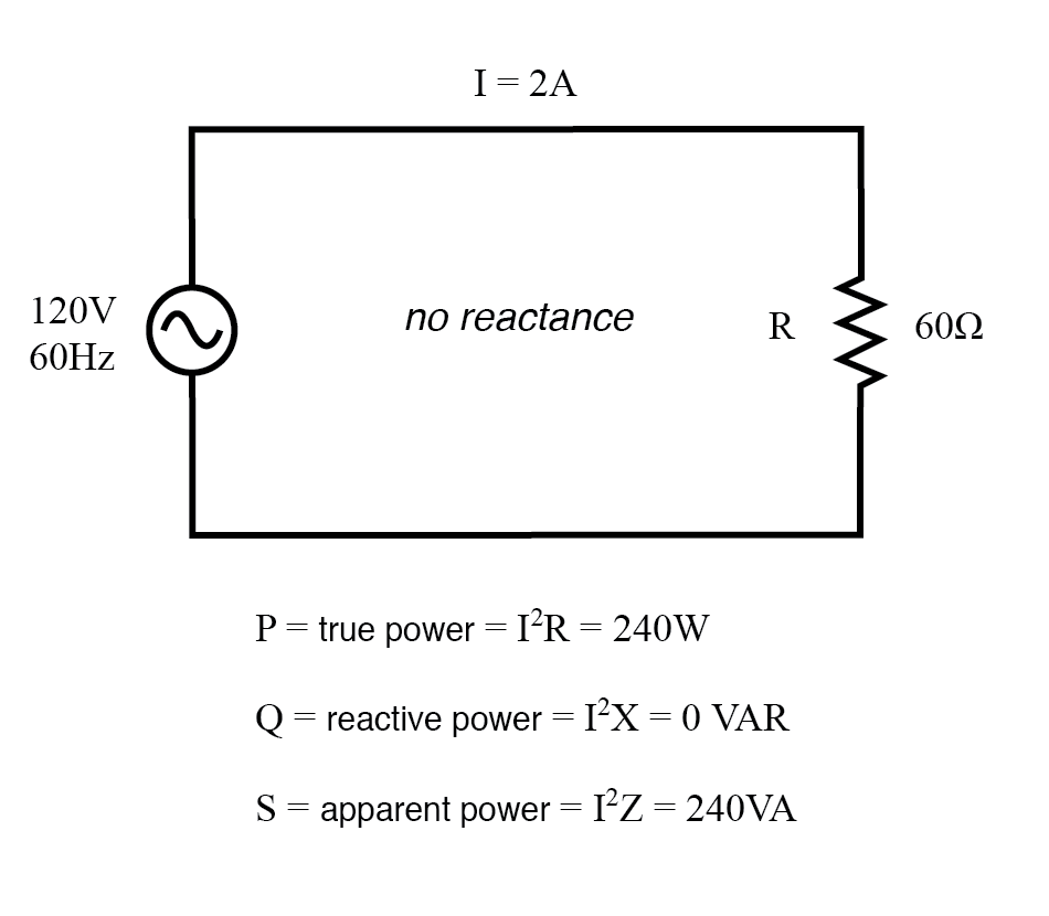
True, reactive, and apparent power for a purely resistive load.
Reactive Load Only
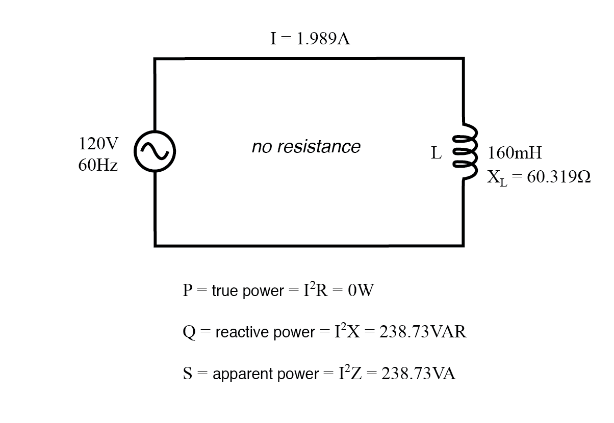
True, reactive, and apparent power for a purely reactive load.
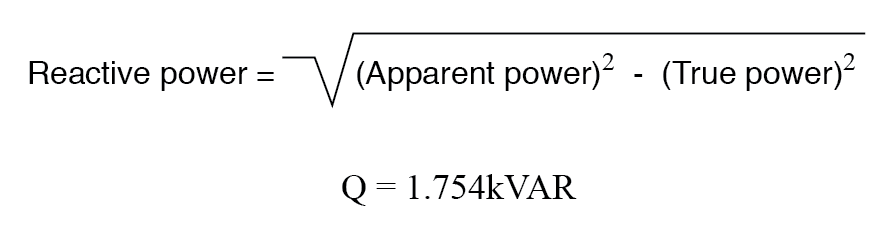
Resistive/Reactive Load
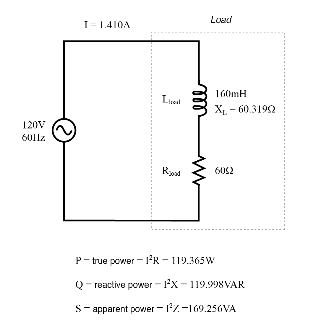
True, reactive, and apparent power for a combined resistive/reactive load.
The Power Triangle
The interrelationship between true, reactive, and apparent power can be visualized as a right‑angled triangle—commonly called the power triangle:
Power triangle: apparent power (hypotenuse), true power (adjacent), reactive power (opposite).
Using basic trigonometry, you can solve for any one side given the other two or an angle. The angle between voltage and current, known as the power factor angle, is the phase angle of the circuit’s impedance.
Key Takeaways- True power (P) is the real energy consumed and is measured in watts.
- Reactive power (Q) is energy that oscillates between the source and the reactive elements, measured in VAR.
- Apparent power (S) is the combined effect of both types and is measured in VA.
- The three powers form a right‑angled triangle: S² = P² + Q², and the power factor = P / S.
- Accurate power calculations require using magnitudes of voltage, current, and impedance.
- AC Power Worksheet
Industrial Technology
- Transformers: Advanced Impedance Matching & Specialized Applications
- Understanding Power in Resistive and Reactive AC Circuits
- Gallium Nitride Amplifiers: Powering 5G and the Road to 6G
- Designing Rugged Power Supplies for Harsh Industrial Environments
- Mastering Current, Power, and Torque in Variable Speed Drives
- Friction Drive vs Engagement Drive: Key Differences Explained
- Understanding Reactive Power: Key Insights for Power System Reliability
- Power & Energy Calculator – Precise kWh Estimation Tool
- Harnessing Wind Power: Strategic Asset Management for a Greener Future
- Reliable Power & HVAC Rentals for Seamless Climate Control