


Transformers: Advanced Impedance Matching & Specialized Applications
Impedance Matching
Transformers can step voltage and current between primary and secondary windings, enabling the conversion of a load’s impedance to a level that matches the source. This capability is critical for efficient power transfer and is widely employed in industrial, audio, and power‑distribution systems.
Consider a resistive heating element that dissipates 1 kW. Two identical heaters may share the same power rating yet operate at different voltage‑current combinations: one at 250 V/4 A (62.5 Ω) and another at 125 V/8 A (15.625 Ω). The 250‑V heater has a higher impedance than the 125‑V heater. If the 250‑V heater is connected directly to a 125‑V supply, the current would drop to 2 A, yielding only 250 W—just a quarter of its rated power.
Using a step‑up transformer, however, allows the 250‑V heater to be powered from a 125‑V source while maintaining full power dissipation. The transformer adjusts both voltage and current, and consequently transforms the load impedance as well. In this case, the primary sees a 15.625 Ω load, and the voltage/current ratio of 2:1 leads to an impedance ratio of 4:1 (the square of the voltage ratio).
Impedance transformation is valuable because it lets a load receive its full rated power even when the supply voltage is not directly compatible.
Impedance, Current, and Voltage Transformation Ratios
The primary circuit of a step‑up transformer displays 125 V at 8 A, which corresponds to a 15.625 Ω load. Thus, the transformer has not only stepped voltage and current but also transformed the load impedance from 62.5 Ω to 15.625 Ω. The relationship is: \[\left(\frac{V_s}{V_p}\right)^2 = \frac{Z_s}{Z_p}\] For a 2:1 voltage ratio, the impedance ratio becomes 4:1.
Application of the Maximum Power Transfer Theorem to Transformers
The Maximum Power Transfer Theorem states that a load receives maximum power when its impedance equals the source (Thevenin) impedance. In AC circuits, impedance replaces resistance in this principle. Proper impedance matching is especially important in radios, transmitters, and audio amplifier‑speaker systems.
For example, an amplifier with an internal impedance of 500 Ω driving an 8 Ω speaker delivers far less than its rated power and wastes energy as heat. A step‑down transformer can match the 500 Ω source to the 8 Ω load, achieving near‑optimal power transfer.
Description of Impedance Matching
To match 500 Ω to 8 Ω, the transformer’s turns ratio must be the square root of 62.5:1, which is approximately 7.91:1. With this ratio, the speaker presents the amplifier with the correct load, allowing efficient power delivery.
Impedance matching is analogous to selecting the appropriate gear on a bicycle. The gear ratio ensures the rider’s legs spin at an optimal speed (60–90 RPM) regardless of terrain. Similarly, transformers adjust voltage and current levels to match source and load impedances.
Impedance Matching Transformers
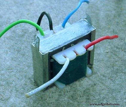
Impedance‑matching transformers share the same construction as other transformers but are specifically tuned for optimal load matching. A compact audio‑frequency matching transformer (≈2 cm wide) is shown below:
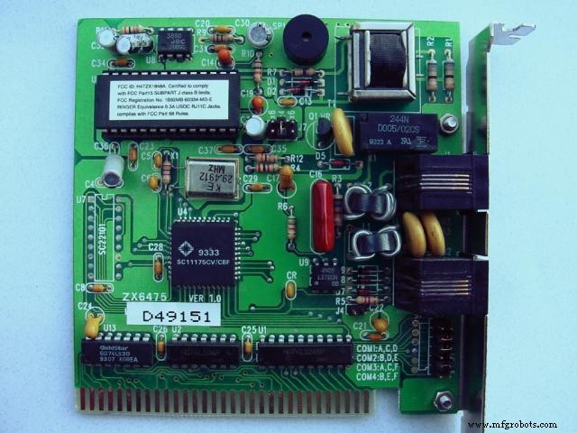
Another example can be seen on a printed circuit board, where a small transformer labeled T1 matches the surrounding circuitry:
Potential Transformers
Potential transformers (PTs) step down high voltages to safe, instrument‑compatible levels while providing electrical isolation. PTs are indispensable for measuring system voltages such as 13.8 kV without exposing personnel or instruments to dangerous potentials.
By using a precision step‑down transformer, a PT reduces the 13.8 kV to a standard 120 V secondary that can be read by a conventional voltmeter. The transformer maintains a constant ratio, ensuring accurate scaling of the measured voltage.
Typical PTs are built with a 120‑V secondary and a 150‑V full‑scale voltmeter range. Custom winding ratios can be fabricated to accommodate any application, simplifying standardization of measurement instruments.
Current Transformers
Current transformers (CTs) are the dual of PTs. They step down high line currents to a safe range (0–5 A) for ammeter measurement. CTs are often toroidal, with the power conductor passing through the core as a single‑turn primary.
Example: a CT with a 50:5 ratio will produce 5 A on its secondary when the line carries 50 A. CTs must never be operated with an open secondary; otherwise, dangerously high voltages will appear. Therefore, a short‑circuit switch is typically installed in parallel with the secondary for safe maintenance.
Air Core Transformers
Air‑core transformers lack a ferromagnetic core, eliminating core losses such as eddy currents and hysteresis. Though coupling is lower than iron‑core designs, air‑core transformers are ideal for high‑frequency applications where core losses would otherwise dominate.
They are used in RF circuits, often paralleled with capacitors to achieve resonance. Small air‑core transformers are common in radio receivers, while larger coils are used in high‑power transmitters. Toroidal forms minimize stray coupling and improve efficiency.
Tesla Coil
The Tesla coil is a resonant, air‑core, step‑up transformer that produces extremely high voltages at high frequency. Its primary circuit is driven by a high‑voltage, low‑frequency source and a spark gap, which charges a capacitor and initiates resonant oscillation. The secondary coil, tuned to the same resonant frequency, discharges through the spark gap, generating visible high‑voltage discharges.
Tesla coils are primarily educational and demonstration devices, but they exemplify the principles of resonant transformers and high‑frequency voltage generation.
Saturable Reactors
A saturable‑core reactor is a specialized inductor whose inductance can be modulated by a DC current through a second winding. When the core saturates, its inductance drops, reducing impedance and allowing controlled current flow through the power winding.
By arranging two reactors with out‑of‑phase control windings, symmetrical control over the AC cycle is achieved, preventing voltage spikes in the DC supply and ensuring balanced power modulation.
Although bulky, saturable reactors (or magnetic amplifiers) provide rugged, failure‑tolerant control of large AC power with a single electrical signal.
Scott‑T Transformer
The Scott‑T configuration converts between two‑phase and three‑phase systems, enabling the use of legacy two‑phase equipment on modern three‑phase transmission lines. It employs a center‑tapped transformer (T1) and an 86.6 % tap transformer (T2) to produce three balanced phases from a two‑phase input.
Mathematically, the T1 1:1 ratio yields a 0.5 V component on each side, while T2 provides 0.866 V at 90°, resulting in 120° phase separation in the three‑phase output.
Linear Variable Differential Transformer (LVDT)
An LVDT is a robust displacement transducer that uses an AC‑excited primary winding and two secondaries on an air‑core. A movable ferromagnetic slug changes the coupling between the primary and secondaries, producing a differential voltage proportional to displacement.
LVDTs can measure displacements from fractions of a millimeter to half a meter and are preferred in harsh environments due to their mechanical ruggedness.
Review
- Transformers can transform impedance in addition to voltage and current, enabling efficient power transfer.
- A Potential Transformer (PT) provides a precise voltage step‑down for high‑voltage measurement.
- A Current Transformer (CT) steps down line current for safe ammeter use.
- Air‑core transformers lack a magnetic core, ideal for high‑frequency applications.
- The Tesla coil is a resonant, air‑core step‑up transformer producing very high AC voltages.
- A saturable reactor uses a DC control winding to modulate the inductance of a power winding.
- A Scott‑T transformer converts 2‑phase to 3‑phase power (and vice versa).
- An LVDT is a distance‑measuring device using a movable core to vary coupling.
Related Worksheets
- AC Metrology Worksheet
- Impedance Matching With Transformers Worksheet
Industrial Technology
- Molybdenum and Its Alloys: Key Applications in Material Processing
- Special Oxide Refractories: Types, Applications, and Industrial Benefits
- Understanding Resistance, Reactance, and Impedance in AC Circuits
- Mastering Series RLC Circuit Analysis: From Impedance to KVL
- Step‑Up and Step‑Down Transformers Explained: Voltage, Current, and Power Distribution
- Practical Considerations in Transformer Design: Power, Losses, and Performance
- True, Reactive, and Apparent Power
- Artificial Intelligence: Evolution, History, and Real-World Applications
- Center‑Tapped Transformers Explained: How They Work and Where They’re Used
- Mastering High‑Speed PCB Power: Analyze and Eliminate Impedance for Reliable Performance