


Step‑Up and Step‑Down Transformers Explained: Voltage, Current, and Power Distribution
Previous sections illustrated transformer simulations where the primary and secondary windings had equal inductance, resulting in roughly equal voltage and current on both sides.
When the inductances differ, the transformer behaves differently.
transformer
 v1 1 0 ac 10 sin
 rbogus1 1 2 1e-12
 rbogus2 5 0 9e12
 l1 2 0 10000
 l2 3 5 100
 k l1 l2 0.999
 vi1 3 4 ac 0
 rload 4 5 1k
 .ac lin 1 60 60
 .print ac v(2,0) i(v1)
 .print ac v(3,5) i(vi1)
 .end
freq          v(2)        i(v1)
6.000E+01     1.000E+01   9.975E-05    Primary winding

freq          v(3,5)      i(vi1)
6.000E+01     9.962E-01   9.962E-04    Secondary winding
Notice how the secondary voltage is approximately ten times lower than the primary voltage (0.9962 V vs. 10 V), while the secondary current is roughly ten times higher (0.9962 mA vs. 0.09975 mA).
This is a classic step‑down transformer: it reduces voltage by a factor of ten and increases current by the same factor.
Turns ratio of 10:1 yields a 10:1 primary‑to‑secondary voltage ratio and a 1:10 current ratio.
What Are Step‑Up and Step‑Down Transformers?
Transformers are indispensable for modern power systems. By stepping voltage up and current down, they enable efficient long‑distance transmission, minimizing line losses and enabling the use of high‑voltage, low‑current power over extensive networks.
At both the generation plant and the consumer side, dedicated transformers reduce voltage to safer, more economical levels.
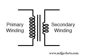
A transformer that raises the voltage from primary to secondary (more secondary turns than primary) is called a step‑up transformer. The opposite, which lowers voltage, is a step‑down transformer.
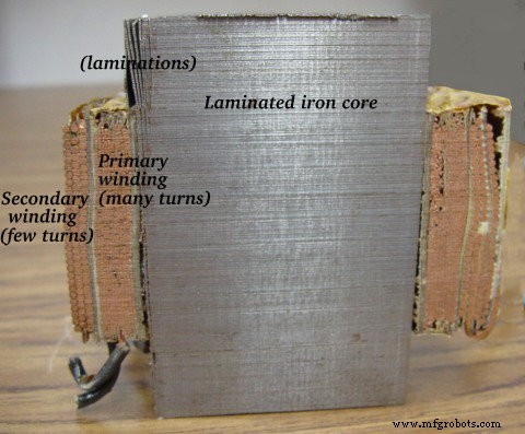
Transformer cross‑section: primary (many turns) and secondary (few turns) windings.
In a step‑down unit, the secondary must carry the higher current, so it is wound with larger‑gauge wire, while the primary can use thinner wire.
Reversibility of Transformer Operation
Transformers can, in principle, be operated in reverse—applying AC to the secondary and drawing power from the primary. This can turn a step‑up into a step‑down and vice versa, provided the winding voltages and currents remain within their original design limits to avoid inefficiency or damage.
Transformer Construction Labels
Industry practice often labels windings to avoid confusion. The higher‑voltage winding receives an “H” designation (H1, H2, …), while the lower‑voltage winding is labeled “X” (X1, X2, …). These conventions help technicians identify primary and secondary leads, especially in complex installations.
Practical Significance of Step‑Up and Step‑Down Transformers
Transformers only redistribute existing power; they do not create it. The product of voltage and current (power) remains constant—subject to a few percent loss from core and copper losses—honoring the Law of Conservation of Energy.
Before efficient transformers existed, motor‑generator sets performed voltage conversion. Although efficient, these machines involved two stages of conversion, reducing overall efficiency to around 90% or less and introducing mechanical wear.
In contrast, transformers have no moving parts, achieve high efficiencies (often >98%), and are essential for the reliable, economical distribution of electricity.
However, transformers cannot change the frequency of AC power or convert between AC and DC. For such tasks, motor‑generator sets or power electronics are required.
Motor‑generator sets also provide kinetic energy storage: if the primary supply is interrupted, the rotating mass can continue to drive the generator briefly, smoothing out transient glitches.
Analysis of Step‑Up and Step‑Down Transformer Operation
The SPICE results illustrate that the inductance ratio of the windings determines the voltage and current ratios. In our example, the primary inductor (l1) has 10 000 H versus 100 H for the secondary—an inductance ratio of 100:1.
Because inductance is proportional to the square of the number of turns (L ∝ N²), a 100:1 inductance ratio corresponds to a 10:1 turn ratio. Consequently, the voltage ratio and current ratio also equal 10:1.
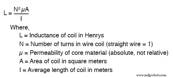
Inductance ∝ N².
Thus, the transformer’s transformation ratio is simply the ratio of primary to secondary turns.
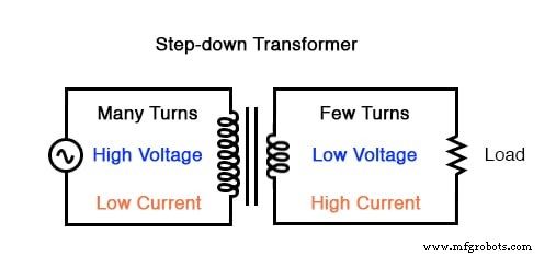
Step‑down transformer: many turns on the primary, few turns on the secondary.
Like gear trains that exchange speed and torque, transformer turn ratios trade voltage for current (or vice versa).
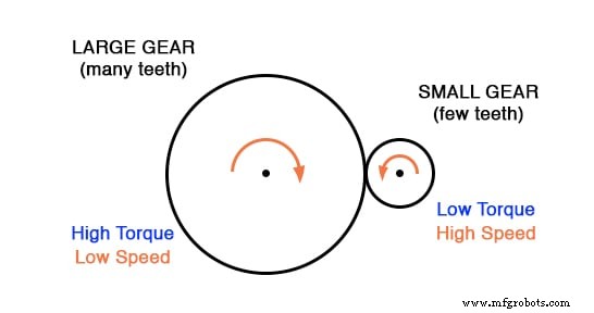
Gear analogy: reducing torque while increasing speed.
Large power‑distribution transformers can be the size of a house. The image below shows a substation transformer standing roughly twelve feet tall.
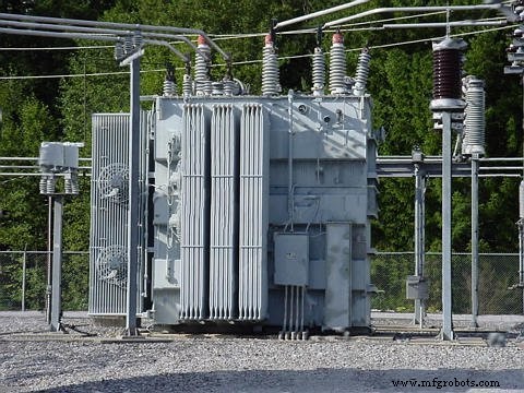
Substation transformer.
Review
- Transformers change voltage by the ratio of primary to secondary turns.
- A step‑up transformer raises voltage; a step‑down transformer lowers it.
- The transformation ratio equals the square root of the primary‑to‑secondary inductance ratio.
See the Step‑Up, Step‑Down, and Isolation Transformers Worksheet for practice problems.
Industrial Technology
- Transformers with Multiple Windings: From Taps to Variacs – A Comprehensive Guide
- Transformers: Advanced Impedance Matching & Specialized Applications
- Four Key Tests to Evaluate Power Transformer Efficiency
- Electrical Transformers Explained: Function, Design, and Industrial Applications
- Accurate kVA Transformer Sizing for Single-Phase & Three-Phase Systems
- Expert Power Transformer Maintenance, Diagnostics & Monitoring – Extend Lifespan
- Comprehensive Guide to Transformer Fire Protection: Causes, Types, and Requirements
- Transformer Testing: Short-Circuit and Open-Circuit Procedures Explained
- Optimizing Power Systems: Parallel Operation of Single‑Phase and Three‑Phase Transformers
- Center‑Tapped Transformers Explained: How They Work and Where They’re Used