


Transformers with Multiple Windings: From Taps to Variacs – A Comprehensive Guide
Transformers with Multiple Secondaries
Transformers are remarkably versatile. While the classic single‑primary, single‑secondary design is widely taught, many practical applications benefit from additional secondary windings. Consider a transformer where three inductors share a common magnetic core, each magnetically coupled to the others.
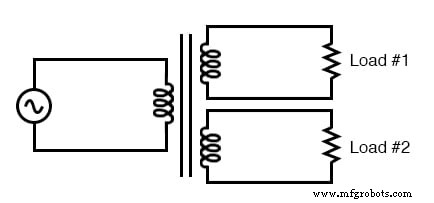
Transformer with multiple secondaries provides multiple output voltages.
In such a configuration, the turn‑ratio rules that govern voltage and current still apply to every pair of windings. You can even design a transformer with one primary, one step‑down secondary, and one step‑up secondary all on the same core.
Historically, this layout was common in vacuum‑tube power supplies, which needed low voltages for filaments (6–12 V) and high voltages for plate drives (hundreds of volts) from a 110 V AC supply.
These transformers provide electrically isolated outputs at very different voltage and current levels, all from a single primary source.
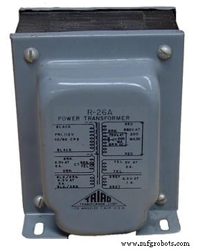
Photograph of a multiple‑winding transformer with six windings, a primary and five secondaries.
The six‑winding transformer shown was designed to supply both the low‑voltage filament supply and the high‑voltage plate drive for vacuum‑tube systems, all from a single 115 V source. The photograph hides 15 conductors that carry the various secondary outputs.
If isolation between secondaries is not critical, a single secondary winding can be tapped at multiple points to create several voltage rails, as illustrated below.
A single tapped secondary provides multiple voltages.
Multi‑Pole Switch Transformer
A tap is simply a connection made along the length of a winding between its ends. The familiar turn‑ratio relationship holds for every tapped segment, allowing a transformer to offer many discrete voltage options.
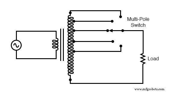
A tapped secondary using a switch to select one of many possible voltages.
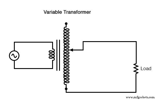
Variable Transformer
Extending the tap concept, a sliding contact can traverse an exposed winding, effectively providing a tap at every turn. This produces a continuous range of output voltages.
A sliding contact on the secondary continuously varies the secondary voltage.
Early model‑train speed controllers in the 1950s and 1960s used this principle. Their transformers stepped down from 110–120 V AC to lower voltages, with the sliding contact providing fine‑tuned speed control without wasting power in a variable resistor.
Large‑scale industrial transformers typically use fixed taps or multi‑pole switches rather than sliding contacts, because moving contacts are impractical at high power levels. Tap switches are usually operated only when the transformer is de‑energized.
Autotransformer
Since a single winding can be tapped to emulate multiple windings, it is possible to eliminate the secondary coil entirely. The result is an autotransformer, a single, tapped coil that steps voltage up or down but does not provide isolation.
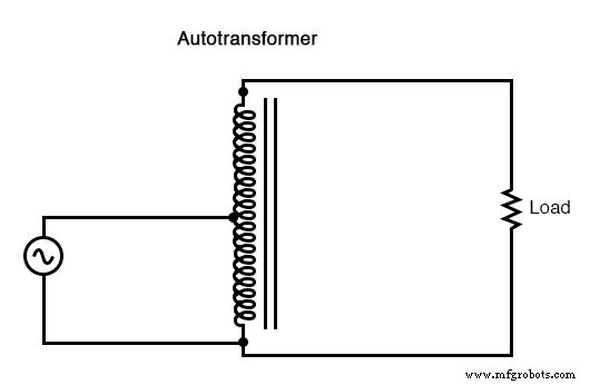
This autotransformer steps the voltage up with a single tapped winding, saving copper, sacrificing isolation.
A step‑down autotransformer would look similar, with the tap positioned to reduce the voltage instead of increasing it.
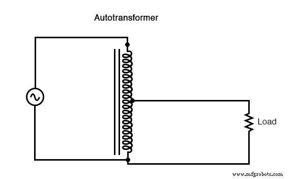
This autotransformer steps the voltage down with a single copper‑saving tapped winding.
Autotransformers are ideal for applications that require a modest voltage boost or reduction. Rather than building a matched pair of primary and secondary windings, a single winding with a tap suffices, reducing cost and weight.
In the “boosting” configuration, the secondary coil’s polarity aligns so that its voltage adds to the primary. In the “bucking” configuration, the secondary’s polarity subtracts from the primary.
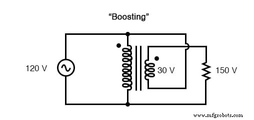
Ordinary transformer wired as an autotransformer to boost the line voltage.
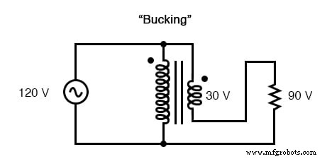
Ordinary transformer wired as an autotransformer to buck the line voltage down.
The key advantage of an autotransformer is the single winding, which lowers material costs and weight compared to a fully isolated transformer with separate primary and secondary windings.
Variac Variable Autotransformer
Autotransformer windings can be tapped to provide multiple ratios, and a sliding contact can turn them into a fully variable device. This form, known as a Variac, is widely used in laboratories and hobbyist circuits.
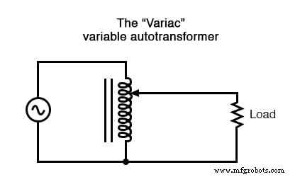
A variac is an autotransformer with a sliding tap.
Bench‑top variacs allow technicians to step down or up household AC voltage with a fine, continuous range of control, simply by turning a knob.
REVIEW:
- Transformers can include multiple primary‑secondary pairs, enabling a range of step‑up and step‑down ratios in a single unit.
- Winding taps segment a single coil into multiple voltage sections.
- Variable transformers use a movable arm to contact the winding at any point, offering continuous voltage adjustment.
- An autotransformer is a single tapped coil that steps voltage without isolation.
- A Variac is a variable autotransformer.
RELATED WORKSHEETS:
- Autotransformers Worksheet
Industrial Technology
- Transformer‑Based Power Supply: Building a Safe 12 VAC Step‑Down Circuit
- Construct a Basic Transformer: Step‑by‑Step Guide
- High‑Sensitivity Audio Detector for Ultra‑Low Electrical Signals
- Using a Musical Keyboard as a Variable‑Frequency AC Signal Generator
- Step‑Up and Step‑Down Transformers Explained: Voltage, Current, and Power Distribution
- Three‑Phase Y and Delta Configurations: Design, Analysis, and Reliability
- Three-Phase Transformer Circuits: Design, Wiring, and Practical Applications
- RF Transformers: Design, Function, and Key Applications
- Understanding the Scott‑T Transformer: Converting Between Two‑Phase and Three‑Phase Power
- Transformer Testing: Short-Circuit and Open-Circuit Procedures Explained