


Understanding Transformer Phase Relationships and the Dot Convention
Why Phase Matters in Transformers
Transformers are inherently alternating‑current (AC) devices, and the relative phase of the primary and secondary windings determines how voltage and current transfer between them. A clear grasp of these relationships is essential for both circuit designers and maintenance professionals.
Simulating Phase Relationships with SPICE
Using a simple SPICE transient analysis, we can visualize how the primary and secondary voltages align in time. The following example models a 10:1 step‑down transformer with a resistive load:
spice transient analysis file for use with nutmeg:
transformer
v1 1 0 sin(0 15 60 0 0)
rbogus1 1 2 1e-12
v2 5 0 dc 250
l1 2 0 10000
l2 3 5 100
k l1 l2 0.999
vi1 3 4 ac 0
rload 4 5 1k
.tran 0.5m 17m
.end
nutmeg commands:
setplot tran1
plot v(2) v(3,5)
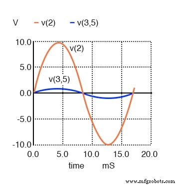
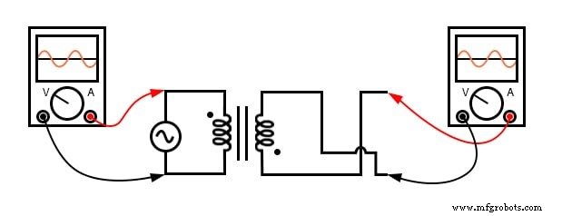
The secondary voltage V(3,5) is in phase with the primary voltage V(2) and reduced by a factor of ten.
In this configuration the secondary voltage is exactly one‑tenth of the primary, while the secondary current rises by a factor of ten. Both waveforms maintain the same phase.
Current Phase Relationship
Using Nutmeg to plot the branch currents:
nutmeg commands: setplot tran1 plot I(L1#branch) I(L2#branch)
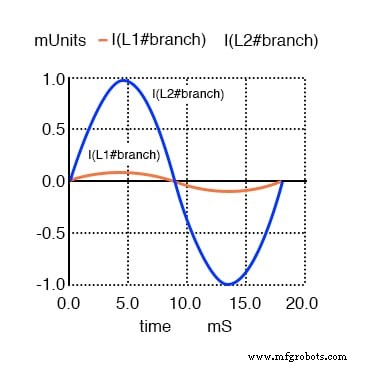
Primary and secondary currents are in phase; the secondary current is ten times larger.
Interpreting Transformer Polarity
Inductors themselves lack polarity markings, so a transformer’s phase relationship depends on how its windings are connected. To standardize this, manufacturers employ the dot convention, a simple yet powerful notation.
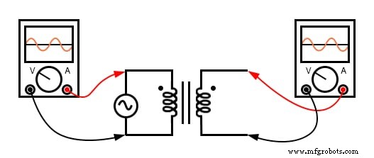
Dots are placed next to corresponding terminals on each winding. When the dots line up on the same side of the transformer, the voltages on the primary and secondary are in phase (zero‑degree shift). If the dots are on opposite sides, the secondary is 180° out of phase.
Opposite dots indicate a 180° phase reversal.
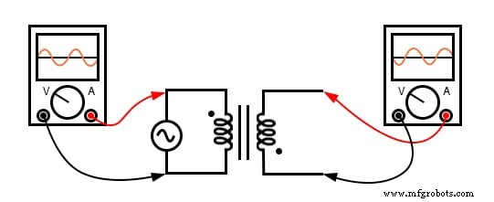
By swapping the connections of the primary or secondary winding, you can intentionally change the phase relationship:
Connecting both windings with matching dots yields an in‑phase relationship.
Key Takeaways
- For an ideal transformer, the primary and secondary voltages and currents are directly proportional and maintain zero phase shift when the dot convention matches.
- The dot convention is the industry standard for indicating winding polarity, ensuring correct phase relationships in circuit design.
Further Learning
Industrial Technology
- Top Applications of Tungsten: From High‑Strength Alloys to Advanced Electronics
- The Four Primary Methods of Permanent Mold Casting
- Understanding Inclusions in Steel: Causes, Types, and Mitigation in Secondary Steelmaking
- CAS-OB Process: Advanced Secondary Steelmaking with Argon and Oxygen Treatment
- Secondary Processing: Advanced Machining, Assembly, and Sealing of Cast Metal Parts
- Why Transformers Fail on DC: The Risks Explained
- Sumpner's Back-to-Back Test: Accurate Transformer Efficiency, Voltage Regulation, and Heating Analysis
- Top Safety Accessories That Keep Warehouse Workers Safe
- Current Transformer (CT): Definition, Applications, and Working Principle
- Primary Air Receivers: Their Role, Benefits, and Optimal Usage