


Construct a Basic Transformer: Step‑by‑Step Guide
PARTS AND MATERIALS
- Steel flat bar, 4 pieces
- Miscellaneous bolts, nuts, washers
- 28‑gauge “magnet” wire (thin‑enamel insulated)
- Low‑voltage AC power supply (≤12 V)
Magnet wire is specifically insulated for use in electromagnets. Its thin enamel coating allows many turns to be wound in a compact coil. While any gauge can be used, 28‑gauge offers the highest turn count for a small‑diameter transformer.
CROSS‑REFERENCES
Lessons In Electric Circuits, Volume 2, Chapter 9: “Transformers”
LEARNING OBJECTIVES
- Understand electromagnetism and its influence on circuit behavior.
- Explore electromagnetic induction and voltage transformation.
- Assess magnetic coupling effects on voltage regulation.
- Analyze how the number of winding turns determines the step‑ratio.
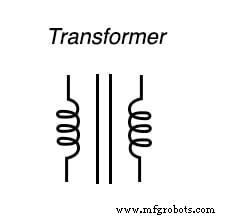
SCHEMATIC DIAGRAM
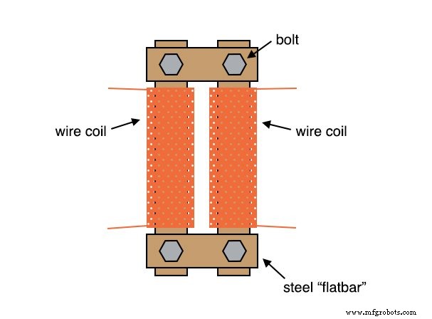
ILLUSTRATION
INSTRUCTIONS
1. Wrap two equal‑length steel bars with a thin layer of electrical tape. 2. Wind several hundred turns of 28‑gauge magnet wire around each bar. Use equal or unequal turns depending on whether you wish the transformer to step‑up or step‑down voltage. Start with equal turns, then experiment.
3. Join the two primary bars to two shorter steel bars, forming a rectangle. Secure the assembly with bolts—drill holes through the bars before winding.
4. Verify insulation: use an ohmmeter to ensure no continuity between winding ends and the steel cores (infinite resistance). Also check continuity between the ends of the wire to confirm the coil isn’t broken. Re‑wind if any fault is detected.
5. Power the transformer with the low‑voltage output of the specified power supply. Never connect directly to mains (120 V) as homemade windings are not rated for high voltage.
6. Measure the secondary voltage with an AC voltmeter. Attach a load (e.g., light bulbs) and record how the voltage sags as current increases.
7. Adjust magnetic coupling by loosening or removing bolts on one short bar to increase reluctance. Observe the impact on output voltage and sag under load.
8. If your transformer has unequal turns, test both step‑up and step‑down configurations with different AC loads.
RELATED WORKSHEET
- Basic AC‑DC Power Supplies Worksheet
Industrial Technology
- Exploring Voltage Addition with Series Battery Connections
- Voltage Divider Lab: Design, Measurement, and Kirchhoff’s Voltage Law Verification
- Thermoelectricity: Understanding Thermocouples and the Seebeck Effect
- Potentiometric Voltmeter: Precise Voltage Measurement with Minimal Loading
- Build a Potato Battery: A Step‑by‑Step Guide to DIY Electrochemical Power
- Construct a Basic Transformer: Step‑by‑Step Guide
- Tachogenerators: Precision Speed Measurement for Industrial Motors and Equipment
- Electromagnetic Induction: The Engine of Modern Electricity
- Understanding AC Waveforms: Sine Waves, Frequency, and Oscilloscope Basics
- Step‑by‑Step Guide to Building a Reliable DC Voltage Booster Circuit