


High‑Sensitivity Audio Detector for Ultra‑Low Electrical Signals
Parts and Materials
- Closed‑cup audio headphones with a high sensitivity rating (dB)
- Female headphone jack (e.g., Radio Shack catalog #274‑312 or equivalent)
- Small step‑down transformer (120 V → 6 V); use the 6‑V secondary winding
- Two 1N4001 rectifier diodes
- 1 kΩ resistor
- 100 kΩ potentiometer (audio‑taper optional; linear works fine)
- Two banana‑jack binding posts (or similar) for the potentiometer circuit
- Plastic or metal enclosure for mounting the components
Choosing headphones is critical: the higher the sensitivity rating in decibels, the better the detector will pick up faint signals. Test several models at a quality audio store and listen for the lowest volume setting that still produces a clear sound.
While premium headphones can enhance performance, a modest pair—such as an old Radio Shack “Realistic” model—has proven adequate for most experiments.
Related Literature
Lessons In Electric Circuits, Volume 1, chapter 8: “DC Metering Circuits”
Lessons In Electric Circuits, Volume 2, chapter 9: “Transformers”
Lessons In Electric Circuits, Volume 2, chapter 12: “AC Metering Circuits”
Learning Objectives
- Master basic soldering techniques
- Understand transformer use for impedance matching
- Detect extremely small electrical signals
- Employ diodes to clip voltage at a maximum level
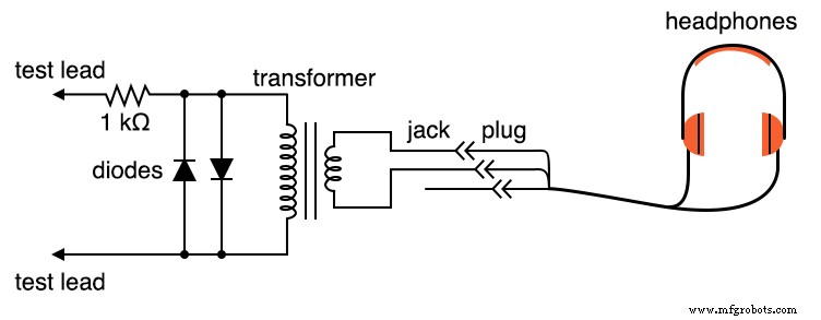
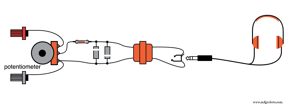
Schematic Diagram
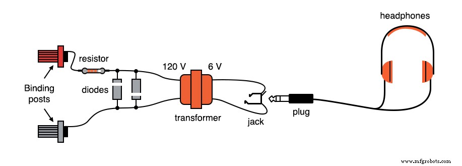
Illustration
Instructions
Follow the construction steps of the “Sensitive Voltage Detector” described in the DC experiments chapter. If you already built that detector, you can skip the initial setup.
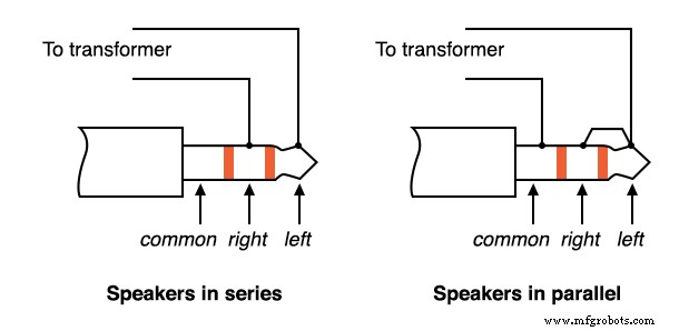
Most headphones are stereo units with a three‑contact plug. Connect to two of those contacts; if you have a mono pair with a two‑contact plug, use those.
You can wire the two headphone drivers in series or in parallel. Series wiring has been found to yield the loudest response for small signals:
Solder all connections solidly—loose contacts add unwanted noise. The two diodes across the transformer’s primary winding, together with the series‑connected 1 kΩ resistor, clip the input voltage to roughly 0.7 V. This limits headphone output and protects against accidental high‑voltage exposure.
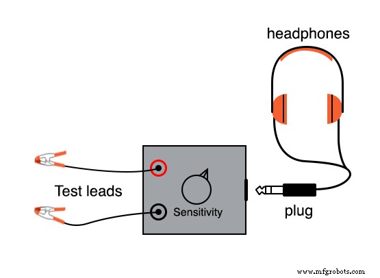
Binding posts provide secure points for banana‑style test probes once the detector is mounted in the enclosure. Use standard multimeter probes or alligator‑clip leads for a reliable connection.
The detector is ideal for balancing bridge circuits, null‑balance voltmeter setups, and for hearing extremely low‑amplitude AC signals in the audio range.
It offers a valuable alternative to an oscilloscope, enabling a different sensory perception of circuit behavior.
When measuring voltages above 1 V, attenuate the detector’s sensitivity with a voltage divider. Insert the divider at the front of the circuit:
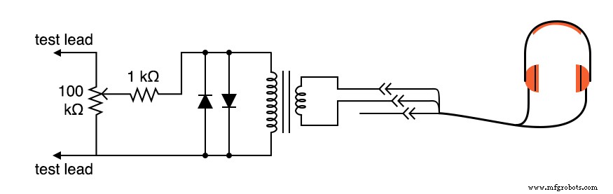
Set the 100 kΩ potentiometer to about half‑range for an unknown signal. Adjust up or down until the audio output is neither too loud nor too faint.
The detector can sense DC and RF signals. A faint “click” is audible whenever the test leads contact or disconnect from the source. With inexpensive headphones, DC currents below 0.1 µA and RF signals up to 2 MHz have been detected.
A striking demonstration is to touch the test leads to the tip of your tongue with maximum sensitivity. The galvanic voltage from metal‑to‑electrolyte contact produces a soft clicking sound each time the leads make contact with wet skin.
Removing the headphone plug and touching the tip of the tongue still produces clicks, but at a lower amplitude. Headphone speakers are low‑impedance devices; they need low voltage and high current for significant sound power.
Impedance (Z) measures opposition to AC, while resistance (R) measures opposition to DC. Both are expressed in ohms (Ω). Most small‑signal sources have internal impedances much higher than the 8 Ω typical of headphones, limiting current delivery.
By matching the headphone impedance to the source impedance with a transformer, the Maximum Power Transfer Theorem ensures optimal sound output. The transformer also generates inductive kickback when the circuit is opened, effectively amplifying tiny DC signals for the headphones.
For long‑term use, build the detector in a permanent enclosure with fixed test lead wires.
Related Worksheets
- Design Project: Sensitive Audio Detector Worksheet
- Impedance Matching With Transformers Worksheet
Industrial Technology
- Sensitive Voltage Detector: Build a High‑Sensitivity Audio Signal Detector
- Build a High‑Performance Class B Push‑Pull Audio Amplifier with TL082 Op‑Amp
- Peak Detector: How It Works and Practical Applications
- Crystal and Transistor Radio Circuits: From Basic Detectors to Integrated AM/FM Receivers
- Transformers with Multiple Windings: From Taps to Variacs – A Comprehensive Guide
- DIY ADXL335 Earthquake Detector – Low‑Power 3‑Axis Accelerometer Project
- Arduino Audio Frequency Detector – Measure Loudest Sound Peaks with High‑Sensitivity Module
- Build a Sensitive Arduino Metal Detector with Ferrous/Nonferrous Discrimination
- Build an Ultra‑Sensitive EMF Detector with Arduino Nano
- Build a Sensitive Metal Detector with Arduino Nano – DIY Guide