


Build a High‑Performance Class B Push‑Pull Audio Amplifier with TL082 Op‑Amp
Components and Materials
- Four 6 V batteries
- Dual op‑amp (TL082 recommended – Radio Shack #276‑1715)
- 1 × NPN power transistor, TO‑220 package (TIP41, #276‑2020 or equivalent)
- 1 × PNP power transistor, TO‑220 package (TIP42, #276‑2027 or equivalent)
- 1 × 1N914 switching diode (Radio Shack #276‑1620)
- 1 × 47 µF electrolytic capacitor, 35 WVDC (Radio Shack #272‑1015 or equivalent)
- 2 × 0.22 µF non‑polarized capacitors (Radio Shack #272‑1070)
- 1 × 10 kΩ linear‑taper potentiometer (Radio Shack #271‑1715)
Use an op‑amp with a high slew rate. Avoid the LM741 or LM1458, which cannot keep pace with the required µV/s transitions.
For best performance, match the NPN and PNP transistors closely. TIP41/TIP42 pairs are ideal, offering 65 W dissipation each. If unavailable, the TIP3055 is an acceptable substitute. Refrain from using large TO‑3 devices; the op‑amp may struggle to drive their bases.
Cross‑References
• Lessons In Electric Circuits, Vol. 3, ch. 4: “Bipolar Junction Transistors”
• Lessons In Electric Circuits, Vol. 3, ch. 8: “Operational Amplifiers”
Learning Objectives
- Construct a push‑pull Class B amplifier using complementary bipolar transistors.
- Understand how crossover distortion manifests in push‑pull stages.
- Apply negative feedback via an op‑amp to correct non‑linearities.
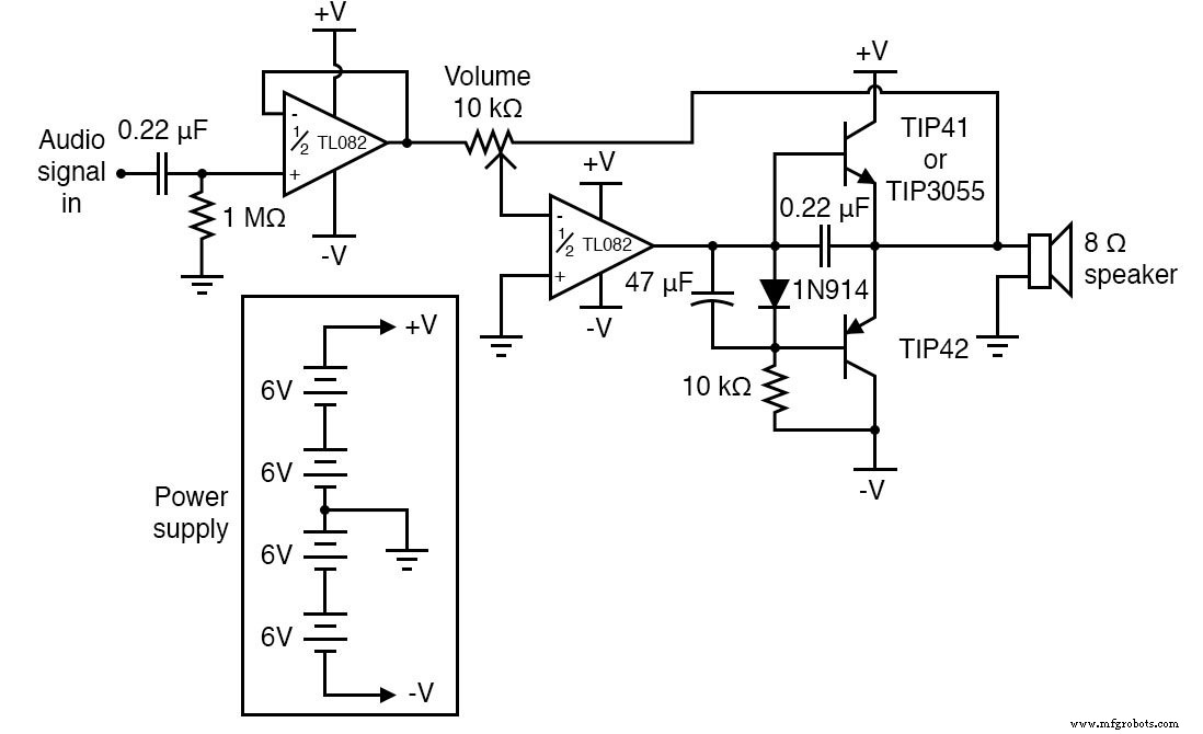
Schematic Diagram
Illustration
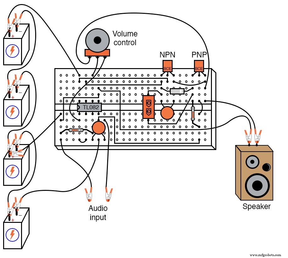
Instructions
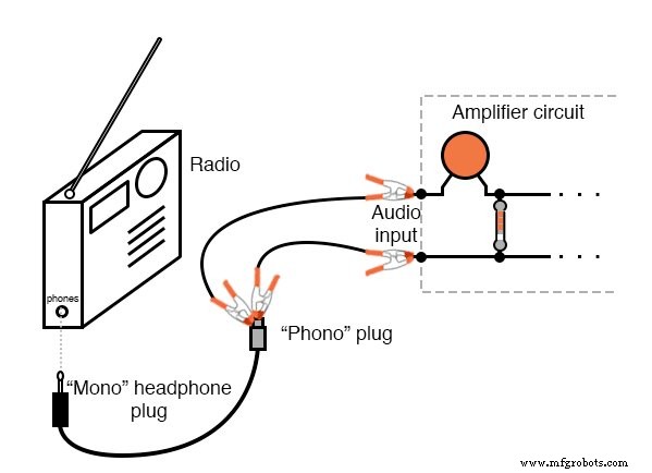
This amplifier is designed to boost signals from small radios, tape decks, CD players, or any line‑level audio source. For stereo output, build two identical units—one per channel—and connect the input to the audio device as shown:
The circuit also performs admirably with high‑quality modular stereo components. It delivers impressive power to large speakers and can operate without heat sinks; however, test the setup with your chosen speakers to confirm thermal stability.
Amplifiers strive to reproduce the input waveform faithfully. Any deviation—distortion—introduces unwanted tones. While perfect fidelity is unattainable, understanding the source of distortion helps refine design. This module focuses on the Class B push‑pull topology, which is common in audio power stages.
In a Class B configuration, one transistor drives the load during the positive half‑cycle (push) while the other handles the negative half (pull). Each transistor remains off for half the cycle, reducing idle power and heat. This efficiency, however, introduces a distinct non‑linearity: crossover distortion.
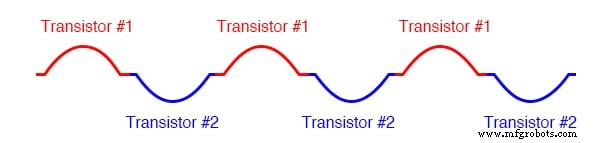
Consider a pure sine wave—constant amplitude, constant frequency. In a push‑pull stage, the transistors alternately amplify the waveform halves. If their hand‑off is not perfectly synchronized, the output will flatten at the zero crossing, producing the familiar “dead zone”:
To mitigate this, bias the transistors so their turn‑on thresholds overlap slightly, creating a Class AB region where both conduct briefly. Although this reduces distortion, it increases quiescent current, leading to extra heat and potential thermal drift.
This design stays in pure Class B—no simultaneous conduction—by employing an op‑amp with negative feedback. The op‑amp detects any dead zone and rapidly drives the transistor bases back into conduction, dramatically reducing crossover distortion without the power penalty of Class AB.
The leftmost op‑amp functions as a buffer, isolating the input capacitor/resistor network and preventing DC bias from reaching the speaker. Without this buffer, low‑frequency response would suffer and high frequencies would be disproportionately amplified.
The second op‑amp serves as an inverting amplifier with a 10 kΩ potentiometer setting the volume. It provides the necessary gain while maintaining a linear relationship between input and output.
Without the op‑amp’s feedback path, the push‑pull pair would experience a 1.4 V dead zone (two Vbe drops), causing noticeable distortion. A common fix is to insert two series diodes across the base drive, dropping ~1.4 V to keep the transistors just at the edge of conduction. However, transistor Vbe changes with temperature while the diode drop remains constant, leading to a drift toward Class AB operation and extra heat.
Temperature‑compensating resistors in the emitter legs can mitigate this, but they introduce series resistance that limits output current.
Our solution relies on the op‑amp’s high slew rate to keep the transistors on precisely. A single diode provides a 0.7 V bias, halving the dead zone. The op‑amp’s feedback is tied to the emitter terminals, allowing it to sense the actual load current and adjust the drive accordingly. This maintains pure Class B conduction while keeping distortion minimal.
The TL082 op‑amp, with its superior slew rate, is essential for tracking the rapid voltage swings needed for low‑distortion operation. Slower op‑amps like the LM741 or LM1458 would lag, allowing distortion to creep in.
Two capacitors complete the circuit: a 47 µF electrolytic in parallel with the bias diode stabilizes the 0.7 V reference, and a 0.22 µF capacitor across the NPN base‑emitter shunts low‑volume crossover distortion.
Related Worksheet
- Class B BJT Amplifiers Worksheet
Industrial Technology
- High‑Sensitivity Audio Detector for Ultra‑Low Electrical Signals
- Designing a High‑Gain Multi‑Stage Common‑Emitter Amplifier with Negative Feedback
- Designing a High‑Gain Differential Amplifier with NPN Transistors
- DIY 12AX7 Vacuum Tube Audio Amplifier – Classic Sound Build
- Understanding Amplifier Gain: Voltage, Current, and Power
- Understanding Amplifier Feedback: Positive vs Negative, and Practical Applications
- Amplifier Input and Output Impedance Analysis
- Crystal and Transistor Radio Circuits: From Basic Detectors to Integrated AM/FM Receivers
- Master Class C Amplifiers: Comprehensive Guide & Expert Insights
- LM1875 Audio Amplifier: In-Depth Guide to Specs, Pinout, and Applications