


Designing a High‑Gain Multi‑Stage Common‑Emitter Amplifier with Negative Feedback
In this tutorial we build a three‑stage common‑emitter amplifier that demonstrates how negative feedback can tame high voltage gain and improve stability.
Parts and Materials
- Three NPN transistors (2N2222 or 2N3403; Radio Shack catalog #276‑1617 is a convenient 15‑piece kit).
- Two 6‑V batteries (or a single 12‑V supply).
- One 10 kΩ single‑turn, linear potentiometer (Radio Shack catalog #271‑1715).
- One 1 MΩ resistor.
- Three 100 kΩ resistors.
- Three 10 kΩ resistors.
Cross‑References
Lessons In Electric Circuits, Volume 3, chapter 4: “Bipolar Junction Transistors”.
Learning Objectives
- Design a multi‑stage, direct‑coupled common‑emitter amplifier circuit.
- Understand the impact of negative feedback on amplifier performance.
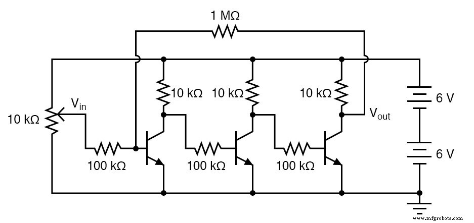
Schematic Diagram
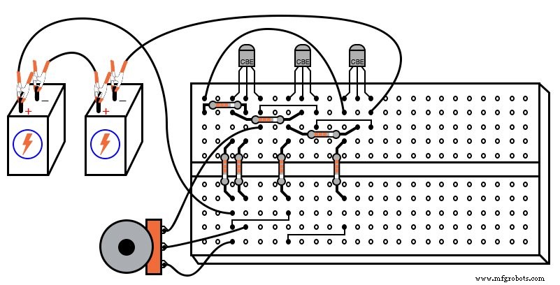
Illustration
Instructions
Connect three common‑emitter stages in series: the collector of each transistor drives the base of the next through a 10 kΩ resistor. This arrangement multiplies the individual stage gains to produce a very high overall voltage gain.
Start by omitting the 1 MΩ feedback resistor. With the transistor parameters set to their maximum, you’ll see an almost unlimited gain that makes the output saturate at the supply rails for modest input signals. If you can’t tune the potentiometer to a stable output in the active region, the basic inversion characteristic will still be evident: as the input rises, the output falls and vice versa.
Because each common‑emitter stage inverts, an even number of stages yields a non‑inverting overall response while an odd number gives an inverted output. Verify this by measuring the collector‑to‑ground voltage at each transistor while sweeping the input potentiometer and observing whether the output rises or drops with an increase in input.
Now add the 1 MΩ feedback resistor from the collector of the last transistor back to the base of the first. Since the three‑stage amplifier is inverted, the feedback signal is inherently negative and will stabilize the circuit, dramatically reducing the sensitivity to input variations.
With feedback in place, the amplifier behaves much more predictably. Record a table of input‑vs‑output voltages and calculate the voltage gain. Try different values for the feedback resistor: decreasing it will raise the gain, while increasing it will lower the gain. The result is a predictable, resistor‑dependent gain rather than one that varies with transistor tolerances.
In practice, real multi‑stage amplifiers incorporate emitter‑to‑ground resistors for bias stability, capacitive coupling between stages, and voltage dividers for biasing. High‑frequency designs often use transformers with resonant capacitors. Nevertheless, the principles demonstrated here underpin the operation of operational amplifiers and many professional amplifier circuits.
Computer Simulation
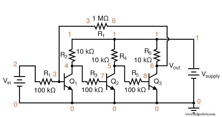
Schematic with SPICE node numbers:
Netlist (copy the following text verbatim into a .cir file):
Multi-stage amplifier
vsupply 1 0 dc 12
vin 2 0
r1 2 3 100k
r2 1 4 10k
q1 4 3 0 mod1
r3 4 7 100k
r4 1 5 10k
q2 5 7 0 mod1
r5 5 8 100k
r6 1 6 10k
q3 6 8 0 mod1
rf 3 6 1meg
.model mod1 npn bf=200
.dc vin 0 2.5 0.1
.plot dc v(6,0) v(2,0)
.end
This simulation plots output voltage versus input voltage, allowing you to compute voltage gain numerically. Experiment with different values of rf and observe how the overall gain changes. The gain can be approximated using only the resistance values of r1 and rf.
Related Worksheet
- Multi‑Stage Transistor Amplifiers Worksheet
Industrial Technology
- Common‑Emitter Amplifier: Design, Measurement, and Feedback Techniques
- Designing a High‑Gain Differential Amplifier with NPN Transistors
- DIY 12AX7 Vacuum Tube Audio Amplifier – Classic Sound Build
- Non‑Inverting Amplifier: Build, Test, and Master Op‑Amp Gain Control
- Understanding Amplifier Gain: Voltage, Current, and Power
- Common‑Collector Amplifier: Emitter‑Follower Fundamentals & Applications
- The Operational Amplifier: Foundations, Features, and Key Applications
- Designing a Practical Differential Amplifier with Controlled Gain
- From Vacuum Tubes to Integrated Circuits: The Evolution of Operational Amplifier Models
- Understanding Voltage Amplifiers: How They Boost Signal Voltage