


Non‑Inverting Amplifier: Build, Test, and Master Op‑Amp Gain Control
PARTS AND MATERIALS
- Operational amplifier: model 1458 or 353 (Radio Shack catalog # 276‑038 / # 900‑6298)
- Three 6 V batteries
- Two 10 kΩ linear‑taper potentiometers (Radio Shack catalog # 271‑1715)
CROSS‑REFERENCES
Lessons In Electric Circuits, Volume 3, Chapter 8: “Operational Amplifiers”
LEARNING OBJECTIVES
- Demonstrate the use of an op‑amp as a single‑ended amplifier.
- Illustrate how divided negative feedback sets controllable gain.
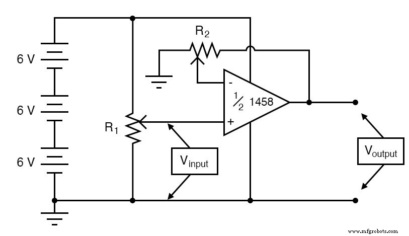
SCHEMATIC DIAGRAM
ILLUSTRATION
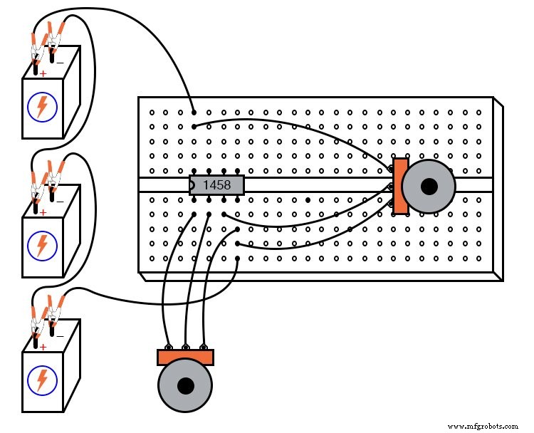
INSTRUCTIONS
The circuit differs from a simple voltage follower only in the feedback path: instead of a direct connection, a voltage‑dividing potentiometer (R₂) feeds back a fraction of the output to the inverting input. This arrangement forces the op‑amp to drive its output to a value that keeps the differential input voltage near zero, producing a voltage gain that is set by the potentiometer’s position.
Set R₂ to roughly the mid‑position. The gain should be close to 2. Measure the input and output voltages at several settings of the input potentiometer (R₁). Then move R₂ to a new position and repeat the measurements. For each R₂ setting, the output‑to‑input ratio remains constant.
Because the output voltage rises in the same direction as the input, the amplifier is classified as non‑inverting. If the output moved opposite to the input, it would be an inverting amplifier. This simple configuration allows precise, adjustable amplification without the complexity of discrete transistor design.
Experiment by varying R₂ to find the maximum and minimum achievable gains. Consider: What is the lowest gain attainable with this setup and why?
COMPUTER SIMULATION
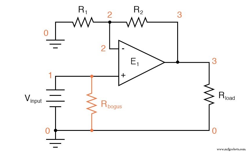
SPICE schematic with node numbers:
Netlist (create a text file containing the following exactly):
Noninverting amplifier
vinput 1 0
r2 3 2 5k
r1 2 0 5k
rbogus 1 0 1meg
 e1 3 0 1 2 999meg
rload 3 0 10k
.dc vinput 5 5 1
.print dc v(1,0) v(3,0)
.end
With R₁ = R₂ = 5 kΩ the simulation represents the mid‑position (50 %). To emulate a 75 % position, set R₂ = 7.5 kΩ and R₁ = 2.5 kΩ.
RELATED WORKSHEET
- Inverting and Noninverting Op‑Amp Voltage Amplifier Circuits Worksheet
Industrial Technology
- Common‑Emitter Amplifier: Design, Measurement, and Feedback Techniques
- Designing a High‑Gain Multi‑Stage Common‑Emitter Amplifier with Negative Feedback
- Designing a High‑Gain Differential Amplifier with NPN Transistors
- DIY 12AX7 Vacuum Tube Audio Amplifier – Classic Sound Build
- Understanding Amplifier Gain: Voltage, Current, and Power
- Common‑Collector Amplifier: Emitter‑Follower Fundamentals & Applications
- The Operational Amplifier: Foundations, Features, and Key Applications
- Designing a Practical Differential Amplifier with Controlled Gain
- From Vacuum Tubes to Integrated Circuits: The Evolution of Operational Amplifier Models
- Understanding Voltage Amplifiers: How They Boost Signal Voltage