


Build a High‑Impedance Voltmeter with TL082 / LM1458 Op‑Amps
Parts and Materials
- Operational amplifier – TL082 (Radio Shack catalog #276‑1715)
- Operational amplifier – LM1458 (Radio Shack catalog #276‑038)
- Four 6 V batteries
- 1 mA meter movement (0‑15 VDC rating, Radio Shack catalog #22‑410)
- 15 kΩ precision resistor (±1 % tolerance)
- Four 1 MΩ resistors (any high‑value resistor will work)
The 1 mA meter movement is marketed as a 0‑15 VDC meter, but it is essentially a 1 mA indicator paired with a 15 kΩ multiplier resistor. If you have this meter, the supplied 15 kΩ resistor can replace the one listed above.
We use a JFET‑input op‑amp such as the TL082 to illustrate how a high‑impedance voltmeter can be constructed. The LM1458 is shown for comparison because it does not suffer from the latch‑up problem that can occur with the TL082.
Very high resistance values are acceptable for the 1 MΩ resistors; they are required only to set the meter’s input impedance and range.
Cross‑References
Lessons in Electric Circuits, Vol. 3, Chap. 8: “Operational Amplifiers.”
Learning Objectives
- Understand voltmeter loading, its causes, and mitigation techniques.
- Build a high‑impedance voltmeter using an op‑amp.
- Recognize op‑amp latch‑up and learn how to avoid it.
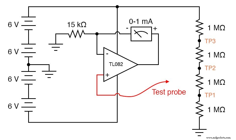
Schematic Diagram
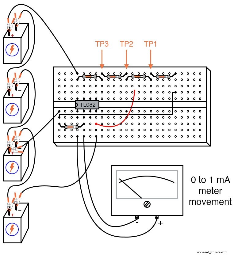
Illustration
Instructions
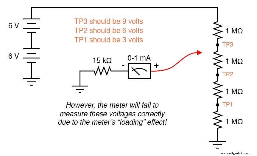
An ideal voltmeter has infinite input impedance, drawing no current from the circuit under test. The higher the meter’s current draw, the greater the measurement error caused by loading – analogous to a tire gauge that sags as it leaks air. This effect is especially pronounced in high‑resistance circuits such as a 1 MΩ voltage divider.
If you simply connect the 1 mA meter movement in series with the 15 kΩ resistor and use it to read the voltages at TP1, TP2, or TP3, you will observe significant errors due to meter loading.
Using the op‑amp configuration described below dramatically reduces loading. The meter movement sits in the op‑amp’s feedback loop, so the current that drives the needle is supplied by the op‑amp’s power rails, not by the test point. The 15 kΩ resistor establishes the full‑scale current for the 1 mA meter.
Build the circuit shown in the schematic and re‑measure TP1, TP2, and TP3. You should now read values close to 3 V, 6 V, and 9 V respectively.
Notice the extreme sensitivity of this design: touching the test probe with one hand and the battery’s most positive terminal with the other will cause the needle to move, because the body’s resistance allows a small current to flow through the meter’s feedback loop. A probe touching ground will correctly read 0 V.
Next, modify the power supply to a split configuration: remove the center‑tap between the 2nd and 3rd batteries and ground the far negative terminal instead.
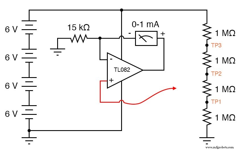
This change raises the test point voltages to 6 V, 12 V, and 18 V. While the 18 V reading will push the meter to its limit, the 6 V and 12 V points will still be accurately measured.
Grounding the test probe now fails to bring the needle to zero. This is a classic op‑amp latch‑up scenario: the JFET input becomes saturated when its common‑mode voltage approaches the negative rail. With a dual supply (+12 V / –12 V), the negative rail is 12 V below ground, so grounding the probe does not violate the common‑mode limits. However, with a single +24 V supply (grounded at 0 V), the probe’s 0 V input reaches the negative rail, triggering latch‑up and causing the output to swing high.
Replacing the TL082 with the LM1458 eliminates this latch‑up, as it tolerates a broader common‑mode range. In general, always ensure that the op‑amp’s supply rails exceed the maximum expected input voltage by at least the device’s common‑mode limits.
Related Worksheet
- Voltage/Current Converter Op‑Amp Circuits Worksheet
Industrial Technology
- Mastering Voltmeter Use: Accurate Voltage Measurement Made Simple
- Mastering Ohmmeter Measurements: A Practical Guide to Resistance Testing
- Build a Custom Analog Multimeter: From Parts to Calibration
- Potentiometric Voltmeter: Precise Voltage Measurement with Minimal Loading
- Testing Diode Polarity and Forward Voltage with a Multimeter
- Safe Meter Usage: A Professional Guide for Electronics Technicians
- Understanding Meter Design: From Classic Galvanometers to Modern Digital Displays
- Designing Precision Voltmeter Ranges: From Sensitive Movements to Full‑Scale Readings
- Multimeters: From Analog to Digital – A Comprehensive Guide
- AC Voltage and Current Meter Design: From Rectification to True‑RMS Measurement