


Safe Meter Usage: A Professional Guide for Electronics Technicians
Mastering safe and efficient meter use is essential for any electronics technician, protecting both the user and ensuring accurate diagnostics.
While the idea of connecting a meter to live circuits can feel intimidating, careful preparation and adherence to best practices eliminate the risk of accidents. Inexperienced handling remains the leading cause of electrical injuries among seasoned technicians.
Multimeters
A multimeter is the most common test instrument in electrical work, capable of measuring voltage, current, resistance, and more. When used by a trained professional it becomes a powerful tool for troubleshooting and safety checks; misuse can turn it into a hazard.
Multimeters come in a variety of brands and models, each offering different feature sets. The illustration below shows a generic digital multimeter, sufficient for teaching core principles.
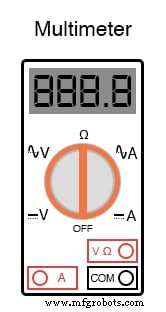
The display is digital, showing up to four digits like a digital clock. The rotary selector offers five positions: two for voltage (V), two for current (A), and one for resistance (Ω). The “Ω” symbol represents ohms, the unit of resistance.
Voltage and current settings are split into DC (solid and dashed lines) and AC (lines with a squiggly curve). Because the meter’s internal circuitry differs for AC and DC, selecting the correct mode is vital.
Multimeter Sockets
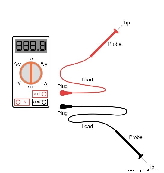
The meter has three sockets for test leads. Black leads plug into the COM (common) socket; red leads plug into either the V or A socket depending on the measurement.
Test leads feature color‑coded, insulated conductors with stiff, pointed probes.
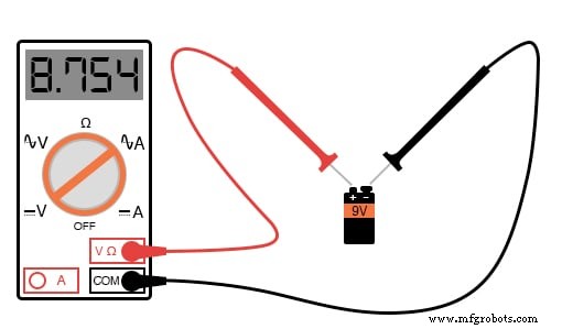
To measure DC voltage from a battery, connect the black lead to COM and the red lead to the V socket, then set the selector to DC V.
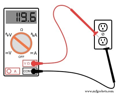
For AC voltage from a wall outlet, keep the leads the same but switch the selector to AC V.
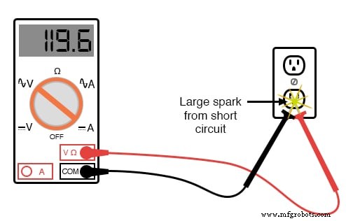
Never let probe tips touch each other while both are connected to a live circuit; this creates a short‑circuit that can spark or ignite.
Voltage Measurement
Voltage is always relative between two points, so a meter must be firmly connected to both. Ideally, one hand should hold each probe; if only one hand can be used, secure the other probe with a spring clip or similar accessory.
Always check for both AC and DC on all pair‑wise combinations of conductors, including between each conductor and ground. For example, with three conductors labeled A, B, and C, you must test A–B, B–C, and A–C in both AC and DC modes, then repeat with A–ground, B–ground, and C–ground, totaling twelve checks.
After completing these tests, verify the meter by measuring a known voltage source, such as a standard wall outlet.
Resistance Measurement
Set the selector to the Ω symbol and keep the leads in the same sockets used for voltage. Place the probes across the component; the meter displays resistance in ohms.

Resistance measurements must be performed on de‑energized components only. The meter’s internal battery injects a small current; any external voltage will distort the reading and can damage the meter.
Continuity and Ohmmeter Mode
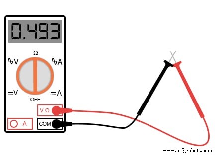
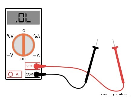
With probes touching each other, a good multimeter shows almost zero Ω. If the leads are open, the display reads “OL” (open loop) or a dash.
Current Measurement
Measuring current is the most hazardous use of a multimeter because the meter must be inserted in series with the circuit. The circuit must be broken, and the meter connected across the break.
Set the selector to AC A or DC A, plug the red lead into the A socket, and connect the probes to the open circuit ends.

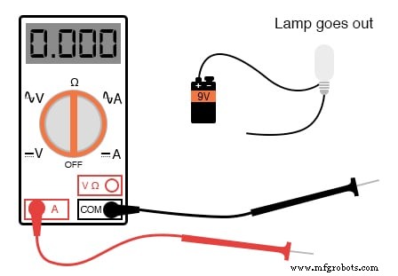
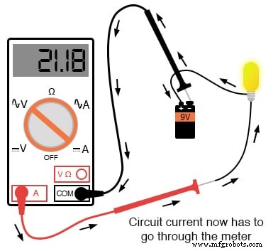
Even low‑voltage circuits can generate sparks when making the final connection, so proceed with caution. High‑power circuits amplify this risk.
Never leave the meter in current mode when measuring voltage. Current‑mode probes present low resistance, creating a short if connected across a high‑voltage source. Many meters beep or display an error when this mismatch occurs, but it is not a substitute for careful switching of both the selector and the lead socket.
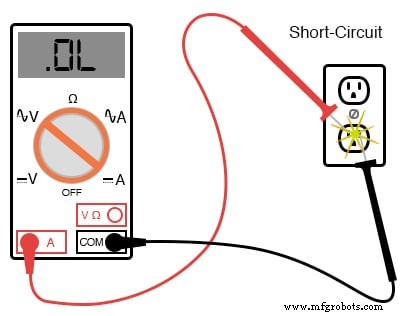
All quality meters contain internal fuses that protect the instrument from overcurrent. A fuse can be tested by placing the red leads together while the meter is set to Ω; a low resistance indicates a good fuse, whereas “OL” indicates a blown fuse.
Mastering voltage, resistance, and current measurement expands a technician’s capabilities and confidence. Regular practice on safe, battery‑powered circuits is the key to proficiency.
Review:
- A multimeter can measure voltage, current, and resistance.
- Voltage requires two circuit points; avoid touching probes together during measurement.
- Always check both AC and DC on all conductor pairs and against ground.
- In voltage mode, the meter’s internal resistance is high to prevent load on the circuit.
- Never measure resistance or continuity on an energized circuit.
- Current measurement requires the meter to be in series with the circuit.
- In current mode, the meter offers minimal resistance to avoid altering the circuit.
Related Worksheets:
- Basic Ammeter Use Worksheet
- Basic Voltmeter Use Worksheet
- Basic Ohmmeter Use Worksheet
- Electric Shock Worksheet
Industrial Technology
- Mastering Voltmeter Use: Accurate Voltage Measurement Made Simple
- Mastering Ohmmeter Measurements: A Practical Guide to Resistance Testing
- Exploring Voltage Addition with Series Battery Connections
- Voltage Divider Lab: Design, Measurement, and Kirchhoff’s Voltage Law Verification
- Thermoelectricity: Understanding Thermocouples and the Seebeck Effect
- Potentiometric Voltmeter: Precise Voltage Measurement with Minimal Loading
- Build a Potato Battery: A Step‑by‑Step Guide to DIY Electrochemical Power
- Low‑Voltage AC Power Supply: Phase‑Shift Circuit Components & Best Practices
- Tachogenerators: Precision Speed Measurement for Industrial Motors and Equipment
- Understanding AC Waveforms: Sine Waves, Frequency, and Oscilloscope Basics