


Mastering Ohmmeter Measurements: A Practical Guide to Resistance Testing
Parts and Materials
- Digital or analog multimeter
- Assorted resistors (Radio Shack catalog # 271-312 – 500‑piece assortment)
- Rectifying diode (1N4001 or equivalent; Radio Shack catalog # 276-1101)
- Cadmium Sulphide photocell (Radio Shack catalog # 276-1657)
- Breadboard (Radio Shack catalog # 276-174 or equivalent)
- Jumper wires
- Paper
- Pencil
- Glass of water
- Table salt
—
This tutorial walks you through measuring the electrical resistance of a wide range of everyday items. While the list above provides a solid starting point, you are free to experiment with any non‑live component you have on hand. Remember, never use an ohmmeter on a live circuit or a source of significant voltage—doing so can damage the meter and pose a safety risk.
—
Cross‑References
Lessons In Electric Circuits, Volume 1, chapter 1: “Basic Concepts of Electricity”
Lessons In Electric Circuits, Volume 1, chapter 8: “DC Metering Circuits”
—
Learning Objectives
- Understand electrical continuity and common points
- Measure resistance accurately and choose the proper meter range
- Interpret the relative conductivity of common materials
—
Illustration
—
Instructions
Resistance quantifies the “friction” that electrons experience as they move through a conductor. It is expressed in ohms (Ω). Begin by setting your multimeter to its highest resistance range. Most meters display this range with the Greek letter Ω or the word “ohms.”
Short the two test probes together; a correctly calibrated meter should read 0 Ω. On an analog meter, the needle will deflect to the far right (zero) and, if needed, you can fine‑tune the zero setting with the adjustment knob.
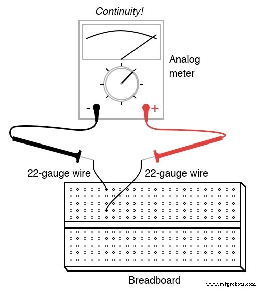
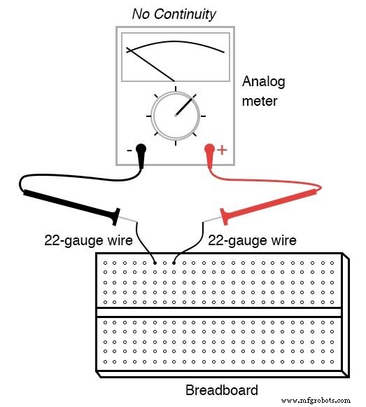
Beyond numerical readings, ohmmeters serve a qualitative role: checking for continuity. If the meter indicates full‑scale deflection when the probes touch the ends of a wire, continuity is confirmed. If the needle remains still, the wire is broken or disconnected.
Measuring Resistance
Digital meters typically display “OL” (Open‑Loop) or a dashed line to denote no continuity. When testing a breadboard, use a 22‑gauge copper wire to bridge the metal spring clips, then probe the terminal pins to confirm the expected connectivity.
Continuity and Commonality
In circuit analysis, a set of points is considered electrically common when the resistance between any two of them is negligible. For example, all points within a breadboard column are electrically common because the internal spring clips provide continuous conductivity. Conversely, points in the same row are not electrically common, as no direct connection exists between them.
Understanding commonality is critical: voltage will not drop appreciably between electrically common points, a fact that underpins many troubleshooting strategies.
Measuring a Resistor
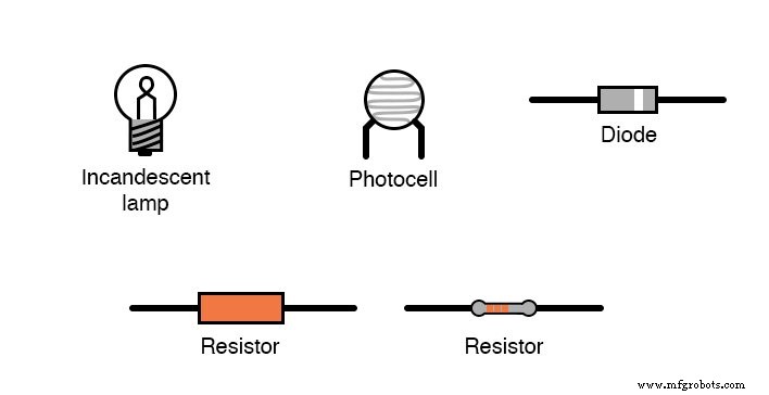
Select a 10 kΩ resistor from your assortment. Its color bands—Brown, Black, Orange, Gold (±5 %)—encode its value. Connect the probes across the resistor and observe the display. If the reading is near zero, switch to a lower range.
Digital meters will show a number close to 10 followed by a “k” (kilo). Reversing the probe polarity on a resistor does not affect the reading, confirming that resistance is direction‑independent.
Avoid touching the probe tips with your fingers during measurement; your body’s resistance (typically >10 kΩ) will add a parallel path and artificially lower the reading. If you wish to test your own body resistance, hold one probe with each hand and adjust the meter range accordingly.
Wet your fingers with plain or salt‑water and re‑measure; the reduced resistance illustrates how moisture lowers skin resistance and increases shock risk.
Measuring Other Materials
Test a rectifying diode with an analog meter. Reverse the probes: the forward direction will show low resistance, while the reverse will display a high value, highlighting the diode’s unidirectional behavior.
For a simple conductor test, draw a thick black line on paper with a pencil and measure resistance between the ends. Shortening the probe spacing will reduce the resistance, demonstrating the inverse relationship between length and resistance.
Finally, connect a cadmium‑sulphide photocell to the meter and observe how its resistance drops under light exposure—a practical illustration of photo‑resistive behavior.
Feel free to experiment with other materials—fabric, plastic, wood, metal, clean water, salt water, glass, diamond, rubber, and oil—always avoiding any component that supplies significant voltage.
—
RELATED WORKSHEETS:
- Basic Ohmmeter Use
Industrial Technology
- Mastering Ohmmeter Measurements: A Practical Guide to Resistance Testing
- Exploring Nonlinear Resistance in Incandescent Lamps: A Practical Lab Guide
- Testing Diode Polarity and Forward Voltage with a Multimeter
- Understanding Electrical Resistance and Circuit Safety
- Resistors: Fundamentals, Types, and Practical Applications
- Safe Meter Usage: A Professional Guide for Electronics Technicians
- Understanding Conductance: The Inverse of Resistance
- Understanding Meter Design: From Classic Galvanometers to Modern Digital Displays
- Designing a Classic Mechanical Ohmmeter: Principles and Practical Considerations
- Calculating Wire Resistance for Voltage‑Drop‑Critical Circuits