


Designing a Classic Mechanical Ohmmeter: Principles and Practical Considerations
Although mechanical ohmmeters have largely been replaced by digital instruments, studying their operation provides valuable insight into analog measurement principles.
Purpose of an Ohmmeter
An ohmmeter measures the resistance between its test leads. The reading is displayed by a mechanical meter movement driven by an electric current. To generate this current, the instrument incorporates an internal voltage source and a set of ranging resistors that ensure the movement receives the correct amount of current for any resistance being measured.
How an Ohmmeter Works
Consider a simple movement powered by a battery:
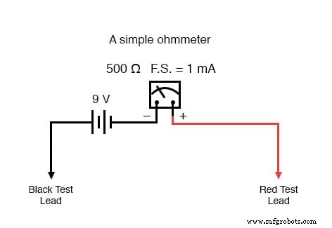
With open leads (infinite resistance), no current flows through the movement, and the needle rests at the far left of the scale. Because the scale is inverted, infinite resistance appears on the left, while zero resistance would lie at the far right.
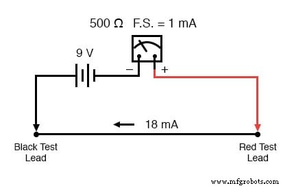
Shorting the test leads together (0 Ω) forces the movement to draw maximum current, limited only by the battery voltage and the movement’s internal resistance. For example, a 9 V battery and a 500 Ω movement would produce 18 mA—far exceeding the 1 mA full‑scale rating and likely damaging the meter.
To prevent this overload and to allow the meter to reach full‑scale deflection at zero resistance, a series resistor is added:
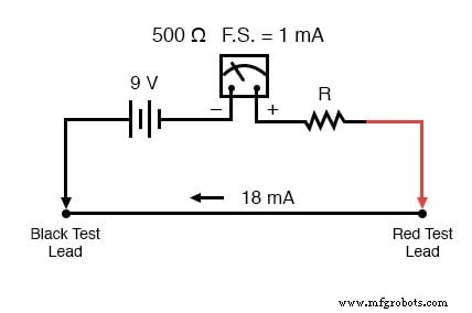
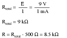
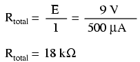
Calculating the appropriate series value (R) involves determining the total resistance required to limit the current to 1 mA at 9 V, then subtracting the movement’s 500 Ω:
Even after adding R, the scale remains “backwards” and stretches from zero to infinity, which raises the question: what resistance value corresponds to half‑scale?
Ohmmeter’s Logarithmic Scale
The answer lies in a nonlinear, logarithmic scale. The meter’s markings are dense at the low‑resistance end and progressively sparser as resistance increases, enabling the needle to reach the left end of the scale when the resistance approaches infinity.
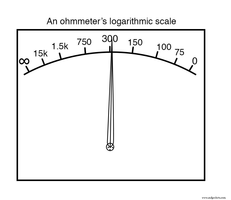
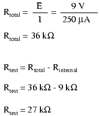
For a full‑scale deflection of 1 mA, half‑scale corresponds to 0.5 mA. With the 9 V supply and the series resistor, the external test resistance required for half‑scale is 9 kΩ:
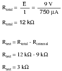
Similarly, 1/4 and 3/4 scale deflections occur at 4.5 kΩ and 13.5 kΩ, respectively:
1/4 scale (0.25 mA):
3/4 scale (0.75 mA):
Thus the complete scale is:
A key limitation of this design is its dependence on a stable battery voltage. As the battery discharges, the meter’s full‑scale deflection at shorted leads will drift, and the 9 kΩ midpoint will no longer correspond to half‑scale. Although compensation techniques exist, they provide only approximate corrections, and the instrument remains unsuitable for precision measurements.
Additionally, an ohmmeter can only be used on circuits that are not powered. Any external voltage present across the test leads will interfere with the internal battery, corrupting the reading and potentially damaging the meter.
- Ohmmeters contain an internal voltage source to supply the measurement current.
- The analog scale is inverted relative to voltmeters and ammeters, with zero resistance at full‑scale and infinite resistance at rest.
- Analog ohmmeters employ a logarithmic scale, expanding at low resistance and compressing at high resistance to span the full range.
- They are not precision instruments due to battery dependence and scale nonlinearity.
- Never use an ohmmeter on an energized circuit; any applied voltage invalidates the measurement.
Related Worksheets
Industrial Technology
- Mastering Ohmmeter Measurements: A Practical Guide to Resistance Testing
- Exploring Nonlinear Resistance in Incandescent Lamps: A Practical Lab Guide
- Understanding Electrical Resistance and Circuit Safety
- Resistors: Fundamentals, Types, and Practical Applications
- Understanding Conductance: The Inverse of Resistance
- Bridge Circuits: Wheatstone, Kelvin, and Their Role in Precise Electrical Measurements
- Battery Construction Fundamentals: Cells, Internal Resistance, and Connectivity
- Calculating Wire Resistance for Voltage‑Drop‑Critical Circuits
- Temperature Coefficient of Resistance: How Temperature Alters Conductivity
- Enhancing Product Durability: Mastering Polyurethane Impact Resistance