


Ammeter Design: Shunt Resistor Techniques for Accurate Current Measurement
Understanding Ammeters
Ammeters are specialized instruments that quantify electrical current in amperes (amps). They consist of a sensitive meter movement that deflects when current flows through it.
Why Shunt Resistors Are Essential
Unlike voltmeters, which use series resistors to limit voltage, ammeters employ shunt resistors placed in parallel with the movement. This configuration diverts the bulk of the current away from the movement while a small, measurable portion continues through the meter.
Designing a Basic Ammeter
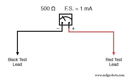
Consider a meter movement that deflects fully at 1 mA with a resistance of 500 Ω. To convert it into a 5 A instrument, we add a shunt resistor so that only 1 mA traverses the movement while the remaining 4.999 A bypasses it.
The voltage across the movement is E = I × R = 0.001 A × 500 Ω = 0.5 V. Because the shunt is in parallel, it shares this same voltage. The shunt current is therefore I_shunt = 5 A – 0.001 A = 4.999 A, giving a required resistance of R_shunt = E / I_shunt ≈ 0.5 V / 4.999 A ≈ 0.100 Ω (100 mΩ).
Re‑labeling the scale from 0 A to 5 A completes the conversion. The following diagram illustrates the mechanical aspect of the adjustment:
Real‑World Ammeter Construction
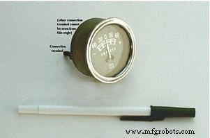
In practice, the shunt resistor is concealed inside the meter’s metal housing. For example, a Stewart‑Warner automotive ammeter can display ±60 A, even though its internal movement only handles milliamps. The shunt is precisely engineered to handle the high current while keeping the movement’s voltage drop negligible.
Multi‑Range Ammeter Design
To offer multiple measurement ranges, several shunt resistors are wired in parallel and selected via a multi‑pole switch. Only one shunt is active at a time, each calibrated for a specific full‑scale value.
For a meter movement rated at 1 mA and 500 Ω, the shunt values for ranges of 100 mA, 1 A, 10 A, and 100 A are:
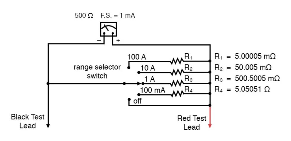
These resistances are extremely low—on the order of a few milliohms—requiring custom fabrication from thick wire or solid metal to ensure durability.
Power Dissipation in Shunt Resistors
Because shunts carry the full current, they can dissipate significant power. For the example above, the power ratings are roughly:
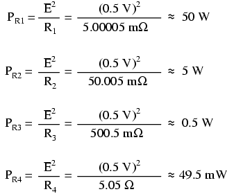
Choosing resistors with adequate power ratings (and often with a safety margin) prevents overheating and preserves accuracy over time.
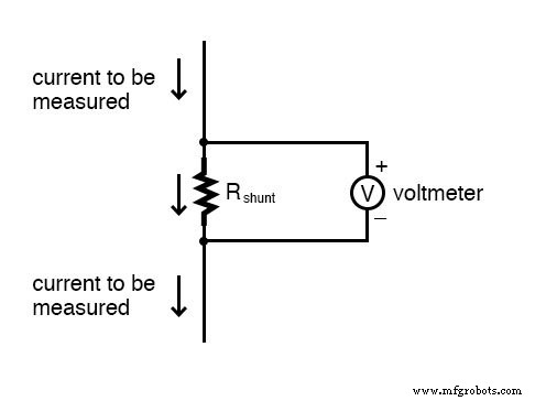
Using Shunt Resistors with Voltmeter Readouts
When a voltmeter has a high input impedance, a low‑value shunt can be placed in the circuit, and the voltage across it can be read directly as current. For instance, a 1 Ω shunt drops 1 V per amp, so a voltmeter reading of 3 V corresponds to 3 A.
In simulation or measurement setups, this technique allows non‑intrusive current monitoring without breaking the circuit:
SPICE Example:
shunt resistor example circuit
v1 1 0 rshunt 1 2 1 rload 2 0 15k .dc v1 12 12 1 .print dc v(1,2) .end
v1 v(1,2) 1.200E+01 7.999E-04
The voltage of 0.7999 V across the shunt corresponds to 0.7999 mA, demonstrating the method’s practicality for low‑current measurements.
Key Takeaways
- Ammeters use parallel shunt resistors to divide current and protect the meter movement.
- Shunt resistors must be low in resistance but robust enough to handle high power dissipation.
- Multi‑range ammeters employ a selector switch to engage the appropriate shunt for the desired scale.
- High‑impedance voltmeters paired with low‑value shunts provide an alternative, non‑intrusive current measurement approach.
Related Worksheets
Industrial Technology
- Measuring Current with an Ammeter: A Practical Guide
- Hands‑On Guide to Current Dividers: Build, Measure, and Simulate with a 6 V Battery
- Common-Emitter Amplifier Limitations: Distortion, Temperature, and High‑Frequency Challenges
- Insulated‑Gate Bipolar Transistors (IGBTs): Merging FET Precision with BJT Power
- DIAC: The Bidirectional Trigger for AC Thyristors
- Understanding Electrical Resistance and Circuit Safety
- Understanding Meter Design: From Classic Galvanometers to Modern Digital Displays
- Designing Precision Voltmeter Ranges: From Sensitive Movements to Full‑Scale Readings
- How Ammeter Resistance Affects Circuit Measurements: Insights & Solutions
- Guarantee First‑Time Success in PCB EMC Design