


How Voltmeter Loading Affects Measurements and How to Minimize It
Every measuring instrument inevitably alters the circuit it probes—much like a tire‑pressure gauge slightly deflates a tire while taking a reading. While some disturbance is unavoidable, thoughtful meter design can reduce it dramatically.
Voltage Divider Circuit
Voltmeter terminals are always connected in parallel with the element(s) under test. Any current drawn by the meter adds to the circuit current, which can change the voltage it reports. A truly ideal voltmeter would have infinite input resistance, drawing no current. In practice, however, even a modern digital voltmeter offers only a finite resistance.
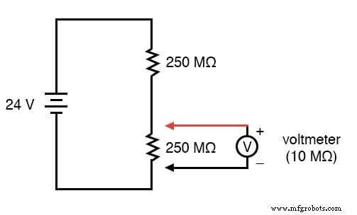
Consider the following extreme voltage‑divider example:
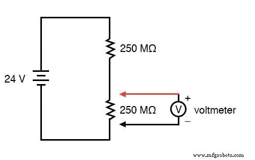
With no meter attached, a 24‑V supply divides evenly across two equal 250 MΩ resistors—12 V across each. When a 10 MΩ voltmeter is connected across the lower resistor, it forms a parallel branch, reducing the effective lower resistance to 9.615 MΩ (250 MΩ || 10 MΩ). The voltage distribution changes drastically: the lower resistor now sees only 0.8889 V, while the upper sees 23.1111 V.
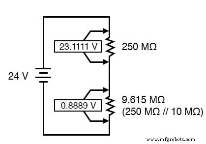
Measured Voltage Divider
With the new effective resistances, the divider produces 23.1111 V across the upper section and 0.8889 V across the lower section. Since the meter itself is part of the lower 9.615 MΩ network, it will display 0.8889 V. The act of connecting the meter changes the circuit’s resistance ratio, so the reading no longer reflects the original 12 V that existed before the meter was attached.
How a Voltmeter Works
Think of a tire‑pressure gauge that consumes a lot of air: the more air it draws, the more it deflates the tire. Similarly, a voltmeter draws current to move its needle. The smaller the current, the less it burdens the circuit. This phenomenon is called loading and is inherent to every voltmeter. The worst case occurs when the meter’s resistance is far lower than the test resistances, but even modest loading will cause the meter to read slightly below the true voltage.
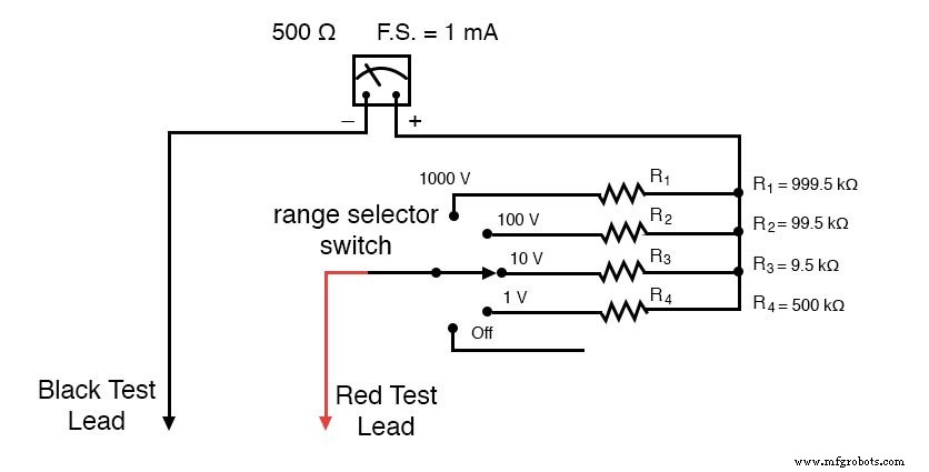
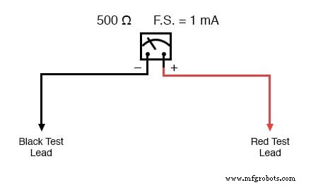
Higher input resistance means lower loading, which is why the ideal voltmeter has infinite internal resistance. Electromechanical meters are rated in ohms per volt (Ω/V) to express the relationship between range and input resistance. For example, a meter with a full‑scale current of 1 mA will have a sensitivity of 1 kΩ/V across all its ranges.
In contrast, most digital meters present a constant input resistance (often around 10 MΩ) regardless of the selected range, simplifying the design but still imposing some loading.
Reducing Meter Loading
Two engineering strategies reduce the impact of a voltmeter:
- Design a low‑current movement. A more sensitive needle requires less current for full‑scale deflection, but the trade‑off is typically reduced durability.
- Use an internal amplifier. The meter’s own battery powers a small amplifier that drives the needle, so only a minute current is drawn from the test circuit. The resulting amplified voltmeter still loads the circuit, but by orders of magnitude less than an unamplified instrument.
Historically, vacuum‑tube voltmeters (VTVMs) performed this amplification. Modern meters rely on solid‑state transistors, which are far more compact and reliable.
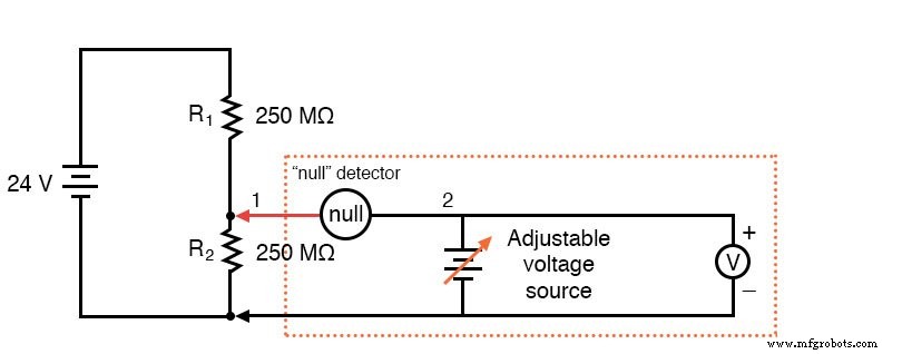
Potentiometric (Null‑Balance) Measurement
For high‑resistance circuits where even an amplified meter may be insufficient, a potentiometric or null‑balance method is ideal. It requires no sophisticated electronics; instead, a precision voltage source is compared against the unknown voltage, and a highly sensitive null detector signals when the two voltages match. At that instant, no current flows through the test circuit, eliminating loading entirely.
Typical null detectors include an electromechanical meter or even a pair of headphones coupled to a small transformer, which audibly clicks when the voltages are balanced.
During measurement, the technician adjusts the reference voltage until the null detector indicates zero differential. The reference voltage is then read on a standard voltmeter—this value equals the voltage across the element under test, free of loading effects.
Key Takeaways
- An ideal voltmeter has infinite input resistance.
- Low input resistance causes the meter to load the circuit and under‑report voltage.
- Vacuum‑tube, transistor, and potentiometric meters all reduce loading; the potentiometric approach can achieve virtually zero load.
- A null detector is a highly sensitive instrument that indicates the absence of voltage between two points, signaling perfect balance.
Related Worksheets
- Basic Voltmeter Use Worksheet
By understanding loading and employing the appropriate measurement technique, you can ensure accurate readings even in the most challenging high‑resistance scenarios.
Industrial Technology
- Circuit With a Switch: A Practical Guide to Basic Electrical Circuits
- Potentiometric Voltmeter: Precise Voltage Measurement with Minimal Loading
- Voltage Follower Amplifier: Design, Build, and Measurement Guide
- Mastering AC Circuit Equations: Impedance, Reactance & Resonance
- Getting Started with SPICE: A Text‑Based Circuit Simulation Tool
- Mastering SPICE Netlist Syntax: Component Naming, Passive & Active Elements, and Source Definitions
- Demultiplexers Explained: How They Route Signals in Digital Circuits
- Understanding TRIACs: Bidirectional Power Control in AC Applications
- How Ammeter Resistance Affects Circuit Measurements: Insights & Solutions
- Understanding the Cost Differences Between Rigid‑Flex and Flex PCBs