


How Ammeter Resistance Affects Circuit Measurements: Insights & Solutions
Like voltmeters, ammeters influence the current they measure, but an ideal ammeter has zero internal resistance to minimize voltage drop across it. This contrasts with voltmeters, which aim to draw minimal current from the circuit.
To illustrate the impact, consider a simple circuit with a 3 Ω resistor and a 1.5 Ω resistor. With the ammeter disconnected, the 3 Ω branch carries 666.7 mA and the 1.5 Ω branch 1.33 A. Introducing an ammeter with 0.5 Ω internal resistance into the 3 Ω branch increases the branch resistance to 3.5 Ω, reducing the measured current to 571.43 mA. Placing the same meter in the 1.5 Ω branch drops the current to 1 A from 1.33 A.
When selecting a shunt resistor for current measurement, choose the lowest practical resistance. Adding unnecessary resistance can alter the circuit’s behavior, especially in high‑precision or high‑current applications.
One elegant solution to eliminate measurement impact is to use the circuit wire itself as the ammeter movement. All current‑carrying conductors produce a magnetic field proportional to the current. By measuring this field, a non‑contact ammeter can determine current without adding any resistance.
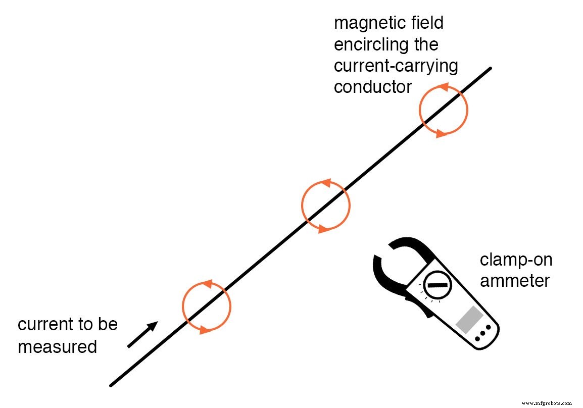
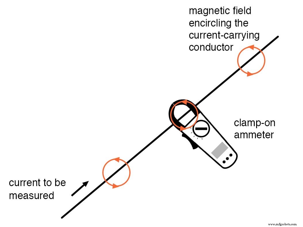
Clamp‑On Ammeters
Clamp‑on meters enclose a single conductor with jaws, allowing quick, safe, and accurate measurements on high‑power circuits. Because they do not insert any resistance into the path, they introduce no measurement error.
The movement mechanism is similar to a classic iron‑vane meter, but instead of an internal coil, a Hall‑effect sensor detects the magnetic field. Modern designs amplify the sensor’s output to provide a voltage proportional to current, which can be read on a connected voltmeter.
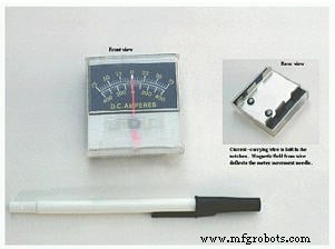
Magnetic‑Field‑Sensing Ammeter
A simpler, less accurate version of the clamp‑on design is shown below. It uses a magnetic field to deflect a needle, offering two measurement ranges (+/- 75 A and +/- 400 A) selectable by positioning the conductor relative to the movement.
Key Takeaways
- Ideal ammeters have zero resistance.
- Clamp‑on meters measure magnetic field, not current flow, making them virtually ideal.
- Non‑contact measurement is fast, safe, and introduces no circuit disturbance.
Related Resources
Industrial Technology
- Measuring Current with an Ammeter: A Practical Guide
- Build a Reliable Current Mirror Circuit: Step‑by‑Step Guide
- Understanding Electrical Resistance and Circuit Safety
- Why Grounding Matters: Preventing Shock from a Single Wire
- How Voltmeter Loading Affects Measurements and How to Minimize It
- Ammeter Design: Shunt Resistor Techniques for Accurate Current Measurement
- Series RC Circuit Analysis: Impedance, Phase Relationships, and SPICE Validation
- Understanding the Cost Differences Between Rigid‑Flex and Flex PCBs
- How Current Limiting Circuits Protect Electronics & Power Supplies
- Building a TDCS Circuit: Step‑by‑Step Guide to Brain Stimulation