


Demultiplexers Explained: How They Route Signals in Digital Circuits
A demultiplexer, often shortened to dmux, is a fundamental digital logic component that takes a single input line and directs the signal to one of several output lines based on select inputs. Unlike a decoder, which maps input codes to one active output, a demultiplexer actively routes the input data to a chosen output channel, making it indispensable for data distribution across multiple devices.
In practice, demultiplexers are ubiquitous in everything from memory address decoding to bus management in microprocessors. Their operation is simple yet powerful, and the industry-standard schematic symbol (see figure below) is widely recognized by electrical engineers.
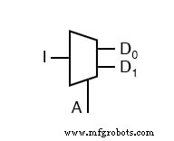
Below is the truth table for a classic 1‑to‑2 demultiplexer. The single input line "I" is routed to either output "D0" or "D1" depending on the state of the select line "S". When S=0, the data appears on D0; when S=1, it appears on D1.
| I | S | D0 | D1 |
|---|---|---|---|
| 0 | 0 | 0 | 0 |
| 0 | 1 | 0 | 0 |
| 1 | 0 | 1 | 0 |
| 1 | 1 | 0 | 1 |
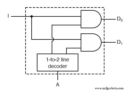
By wiring a 1‑to‑2 decoder to the input, we can express this behavior graphically:
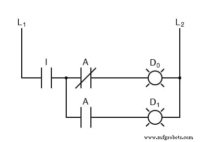
And the resulting logic can be captured in a straightforward gate‑level diagram:
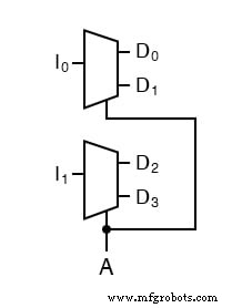
Scaling a demultiplexer is straightforward. To handle more outputs, you can either increase the number of select lines—requiring a larger decoder—or add additional demultiplexing stages for each data line. For example, a "two‑bit 1‑to‑2 demultiplexer" passes two data bits simultaneously to two output channels.
Its schematic is illustrated below, which can also be decomposed into two separate one‑bit 1‑to‑2 demultiplexers without altering functionality:
Or equivalently expressed as:
These diagrams confirm that the two‑bit device behaves as two independent one‑bit demultiplexers working in parallel.
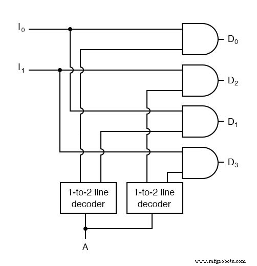
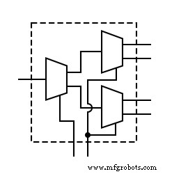
Extending further, a 1‑to‑4 demultiplexer can be constructed by cascading two 1‑to‑2 demultiplexers. The resulting structure allows a single input to be routed to any of four outputs, a common requirement in bus arbitration and address decoding.
For hands‑on practice, refer to the Multiplexers and Demultiplexers Worksheet, which provides exercises to reinforce understanding of signal routing and logic design.
RELATED WORKSHEET:
- Multiplexers and Demultiplexers Worksheet
Industrial Technology
- Circuit With a Switch: A Practical Guide to Basic Electrical Circuits
- Voltage Follower Amplifier: Design, Build, and Measurement Guide
- Mastering AC Circuit Equations: Impedance, Reactance & Resonance
- Getting Started with SPICE: A Text‑Based Circuit Simulation Tool
- Mastering SPICE Netlist Syntax: Component Naming, Passive & Active Elements, and Source Definitions
- Understanding TRIACs: Bidirectional Power Control in AC Applications
- Understanding Electrical Resistance and Circuit Safety
- Understanding Fuses: Types, Ratings, and Safe Installation
- Analyzing Complex RC Circuits Using Thevenin’s Theorem
- Analyzing Circuit Response to Multi‑Frequency Sources