


Multiplexers (MUX) – Design, Truth Tables, and Practical Applications
A multiplexer, commonly abbreviated as MUX, is a digital switching device that routes one of many input signals to a single output line based on selector inputs.
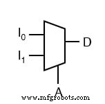
The standard schematic symbol for a multiplexer is illustrated below:
Below is the truth table for a classic 2‑to‑1 multiplexer. The selector bits are A (most significant) and D (least significant), while I0 and I1 are the two data inputs.
| I1 | I0 | A | D | Output |
|---|---|---|---|---|
| 0 | 0 | 0 | 0 | 0 |
| 0 | 0 | 0 | 1 | 0 |
| 0 | 1 | 0 | 0 | 0 |
| 0 | 1 | 0 | 1 | 1 |
| 1 | 0 | 0 | 0 | 1 |
| 1 | 0 | 0 | 1 | 0 |
| 1 | 1 | 0 | 0 | 1 |
| 1 | 1 | 0 | 1 | 1 |
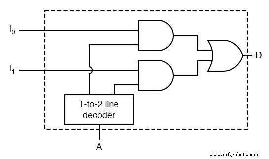
Using a 1‑to‑2 decoder in the control logic simplifies the implementation of this truth table. The decoder generates the two selector signals that enable the appropriate data input path.
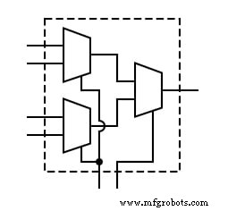
Extending this concept, a 4‑to‑1 multiplexer uses two selector bits to route one of four data inputs to the output. The circuit diagram is shown below:
In practice, the terms multiplexer and demultiplexer often appear together because they share similar symbols and naming conventions. This can lead to confusion; however, a MUX actively routes input to output, while a demultiplexer distributes a single input to multiple outputs.
RELATED WORKSHEET:
Industrial Technology
- Electronics: A Hands‑On Science for All
- Setting Up a Home Electronics Lab: Tools, Work Area, and Supplies
- Mastering Voltmeter Use: Accurate Voltage Measurement Made Simple
- Mastering Ohmmeter Measurements: A Practical Guide to Resistance Testing
- Building and Troubleshooting a Basic 6‑V Battery‑Lamp Circuit
- Measuring Current with an Ammeter: A Practical Guide
- Practical Ohm’s Law Experiment: Measuring Voltage, Current, and Resistance
- Exploring Nonlinear Resistance in Incandescent Lamps: A Practical Lab Guide
- Measuring Power Dissipation in Resistors: A Hands‑On Experiment with Joule’s Law
- Multiplexers (MUX) – Design, Truth Tables, and Practical Applications