


Build a Custom Analog Multimeter: From Parts to Calibration
Parts and Materials
- Meter movement (Radio Shack catalog #22‑410)
- Selector switch, single‑pole, multi‑throw, break‑before‑make (Radio Shack catalog #275‑1386, a 2‑pole, 6‑position unit works well)
- Multi‑turn potentiometers, PCB mount (Radio Shack catalog #271‑342 – 15‑turn, 1 kΩ; #271‑343 – 15‑turn, 10 kΩ “trimmer”)
- Assorted high‑precision metal‑film or wire‑wound resistors (Radio Shack catalog #271‑309, ±1 % tolerance)
- Plastic or metal mounting enclosure
- Three “banana” jack‑style binding posts or equivalent terminal hardware (Radio Shack catalog #274‑662)
The core of any meter is its movement—the needle‑and‑scale mechanism that converts electrical current into visible displacement. A larger, more sensitive movement improves readability and reduces required test currents. While high‑quality movements can be costly, the listed Radio Shack options offer a good balance of performance and price.
The recommended movement is marketed as a 0‑15 V voltmeter, but in practice it functions as a milliammeter with an external multiplier resistor. You may also repurpose the movement from a discarded analog meter; the educational value of the disassembly often outweighs the cost of a new unit.
Resistor choice is critical. Use precision fixed resistors rather than carbon‑composition types, which drift with temperature and aging. Even if stability isn’t your primary goal, precision components make the learning experience more meaningful.
Cross‑References
Lessons In Electric Circuits, Volume 1, Chapter 8: “DC Metering Circuits.”
Learning Objectives
- Understand voltmeter and ammeter design principles
- Implement rheostat‑based range limiting
- Apply calibration theory and practice
- Develop soldering proficiency
Schematic Diagram
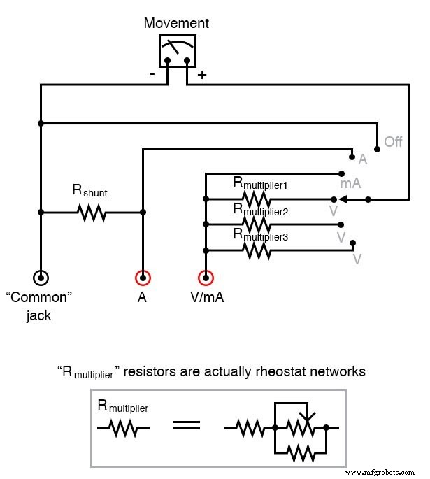
Illustration
Instructions
1. Determine the movement’s full‑scale deflection (FSD) (in mA or µA). Connect the movement to a potentiometer, battery, and digital ammeter in series. Adjust the potentiometer until the needle reaches full‑scale, then read the current. Avoid exceeding the movement’s rated FSD—most are ≤ 1 mA.
2. Measure the internal resistance (Rₘ). Disconnect the test circuit, place a digital ohmmeter across the movement terminals, and record the resistance. Combine the FSD and Rₘ values for later calculations.
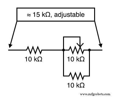
3. Calculate multiplier resistance (Rₘᵤlt) for the desired voltage range. For example, a 1 mA FSD and 400 Ω Rₘ targeting 0‑15 V yields a total resistance of 15 kΩ. Subtract Rₘ to obtain 14.6 kΩ for the multiplier. A practical rheostat network could be a 10 kΩ potentiometer in parallel with a 10 kΩ fixed resistor, all in series with another 10 kΩ fixed resistor.
4. Selector switch wiring:
- Position 1: Directly connect the movement between the Common (black) and V/mA (red) posts—this configures an ammeter with a range equal to the movement’s FSD.
- Position 2: Short the movement’s positive terminal to the negative terminal to protect it from accidental overvoltage.
- Position 3: For high‑current ammeter ranges, use a low‑resistance shunt. Replace 1/4 W resistors with a parallel network of smaller resistors or a precisely notched wire or metal strip. Calibrate by incrementally increasing shunt resistance with a metal file while monitoring a reference current source.
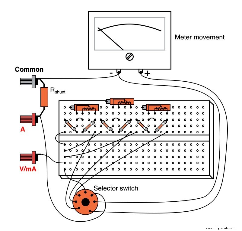
5. Prototyping—Build the circuit on a breadboard first. Adjust rheostat values and perform calibrations in this flexible environment. Once satisfied, transfer the layout to a printed circuit board. Radio Shack’s catalog #276‑170 offers a ready‑made PCB with breadboard‑style footprints.
6. Enclosure—Mount the PCB, wiring, and movement in a sturdy box to protect the meter and provide a professional finish.
While this DIY multimeter lacks resistance measurement, AC capability, and the high precision of commercial units, it offers invaluable insight into instrument fundamentals, circuit design, and calibration techniques. Future projects can extend this design by adding an amplifier stage for improved accuracy and versatility.
Related Worksheets
- Basic Ammeter Use Worksheet
- Basic Voltmeter Use Worksheet
- Design Project: Voltmeter Worksheet
Industrial Technology
- Build a High‑Impedance Voltmeter with TL082 / LM1458 Op‑Amps
- Designing Precision Voltmeter Ranges: From Sensitive Movements to Full‑Scale Readings
- AC Voltage and Current Meter Design: From Rectification to True‑RMS Measurement
- Build a DIY Google Voice HAT for Your Raspberry Pi
- DIY Carbon Fiber Starter Kit – Build Custom Parts Safely & Affordably
- Master Multimeter Testing: A Step‑by‑Step Guide for Electrical & Electronics Components
- Master Office Organization in Manufacturing Plants: Proven Tips for Efficiency & Reduced Stress
- 10 Proven Strategies to Enhance Your Preventive Maintenance Program
- Ensuring High Availability of PCB Files: A Comprehensive Guide
- Build a Digital Arduino Ammeter: Step‑by‑Step Guide to a DIY Current Meter