


Encoder Fundamentals: Designing 2‑to‑1 and 7‑Segment Binary Encoders
What Is an Encoder?
An encoder is a combinational circuit that converts a set of input signals into a binary‑coded output. It is the logical inverse of a decoder. In practice, encoders are used to reduce the number of signals required to represent a set of inputs, which simplifies downstream processing and improves system reliability.
2‑to‑1 Line Encoder
To illustrate the concept, let’s derive the truth table for a simple 2‑to‑1 line encoder by reversing a 1‑to‑2 decoder. The decoder truth table is:
| D1 | D0 | A |
|---|---|---|
| 0 | 1 | 0 |
| 1 | 0 | 1 |
Inverting this relationship gives the encoder truth table:
| D1 | D0 | A |
|---|---|---|
| 0 | 0 | – |
| 0 | 1 | 0 |
| 1 | 0 | 1 |
| 1 | 1 | – |
When both inputs are active (the last row), the output is undefined. In many applications, this situation is handled by adding sequential logic to detect and flag multiple simultaneous activations, ensuring reliable operation.
Encoder Design Applications
A common real‑world application is the binary‑to‑7‑segment display encoder. The seven segments (labeled D6 through D0) must be activated to render decimal digits on a 7‑segment display. The truth table for a 4‑bit binary input (I3…I0) is shown below:
| I3 | I2 | I1 | I0 | D6 | D5 | D4 | D3 | D2 | D1 | D0 |
|---|---|---|---|---|---|---|---|---|---|---|
| 0 | 0 | 0 | 0 | 1 | 1 | 1 | 0 | 1 | 1 | 1 |
| 0 | 0 | 0 | 1 | 0 | 0 | 1 | 0 | 0 | 1 | 0 |
| 0 | 0 | 1 | 0 | 1 | 0 | 1 | 1 | 1 | 0 | 1 |
| 0 | 0 | 1 | 1 | 1 | 0 | 1 | 1 | 0 | 1 | 1 |
| 0 | 1 | 0 | 0 | 0 | 1 | 1 | 1 | 0 | 1 | 0 |
| 0 | 1 | 0 | 1 | 1 | 1 | 0 | 1 | 0 | 1 | 1 |
| 0 | 1 | 1 | 0 | 1 | 1 | 0 | 1 | 1 | 1 | 1 |
| 0 | 1 | 1 | 1 | 1 | 0 | 1 | 0 | 0 | 1 | 0 |
| 1 | 0 | 0 | 0 | 1 | 1 | 1 | 1 | 1 | 1 | 1 |
| 1 | 0 | 0 | 1 | 1 | 1 | 1 | 1 | 0 | 1 | 1 |
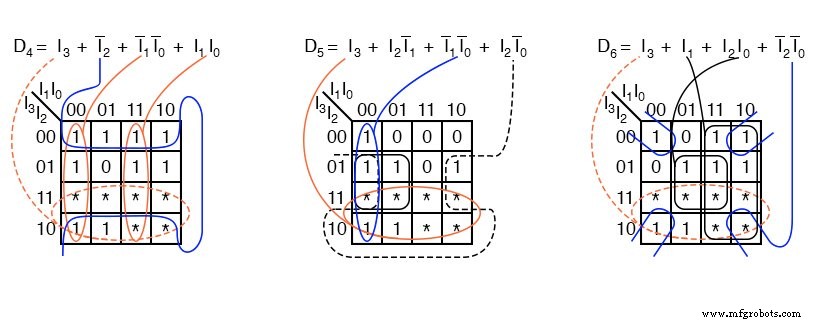
Entries that correspond to non‑existent decimal digits (e.g., binary 1011 and above) can be treated as don’t‑care conditions, allowing the logic to be simplified. Using Karnaugh maps, the minimized equations for each output are derived as follows:
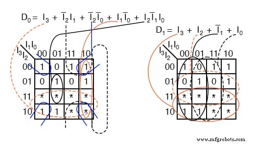
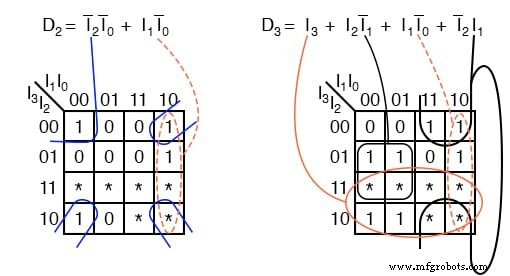
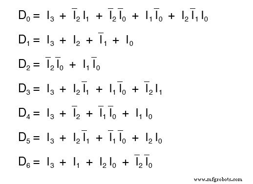
The resulting simplified equations are summarized below:
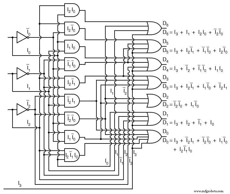
Resulting Circuit Diagram
Implementing the equations with standard logic gates yields the following schematic:
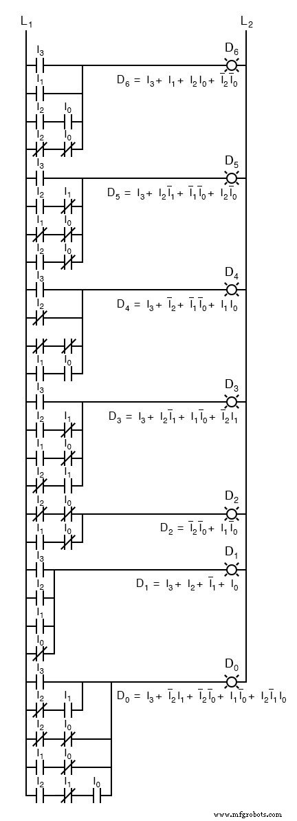
Corresponding Ladder Diagram
For PLC applications, the ladder logic equivalent is also provided:
Related Worksheet
Industrial Technology
- Verilog Priority Encoder: Reliable 4‑Input 8‑Bit Selector
- Trusted Fanuc Encoder Repair Services for Precision Machining
- Top 6 Encoder Repair Tips to Minimize Downtime
- Java 8 Base64: Simple, URL, and MIME Encoding Made Easy
- Create a Rotary Encoder‑Controlled Menu on a Nokia 5110 LCD with Arduino UNO
- Master Rotary Encoders with Arduino: How They Work & Step‑by‑Step Integration
- A Comprehensive Guide to Encoder Types for Precise Motor Control
- Mastering Arduino Rotary Encoders: A Comprehensive Guide to Setup, Types, and Applications
- HT12E Encoder IC Datasheet: Comprehensive Overview & Application Guide
- Efficient Tapping with Sinumerik CYCLE840 and Floating Tapholder – No Encoder Needed