


Component Failure Analysis: Troubleshooting Techniques for Series and Parallel Circuits
The technician’s core duty is troubleshooting: pinpointing and correcting faults in malfunctioning circuits. Effective troubleshooting blends deep knowledge of fundamentals, hypothesis generation, probability assessment, and creative problem‑solving.
While these skills can be framed scientifically, seasoned troubleshooters agree that the craft has an artistic edge and takes years of hands‑on experience to master.
A critical ability is to instantly understand how component failures alter circuit behavior in different topologies. We’ll first examine simple series and parallel configurations, then delve deeper in the Series‑Parallel Combination Circuits chapter.
Analyzing Failures on a Simple Series Circuit
Consider the following ideal series circuit:
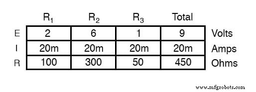
With all components functioning at their proper values, we can mathematically determine all currents and voltage drops:
Shorted Components in a Series Circuit
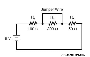
Suppose R2 shorts. A short means the resistor now behaves like a wire with negligible resistance. The circuit effectively contains a jumper across R2. The cause of the short is irrelevant; what matters is its impact.
A shorted R2 reduces the total series resistance. With a fixed source voltage, the overall current must increase, as dictated by Ohm’s Law.
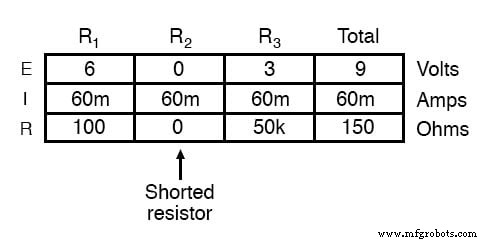
The current rises from 20 mA to 60 mA. Consequently, the voltage drops across the unchanged resistors R1 and R3 increase to absorb the full 9 V. R2, bypassed by the low‑resistance path, experiences zero voltage drop.
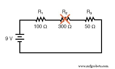
Opened Components in a Series Circuit
If R2 opens—its resistance skyrockets toward infinity—the series network’s total resistance skyrockets, pulling the total current down to zero.
With no current, there are no voltage drops across R1 and R3. The open R2, however, shows the entire supply voltage across its terminals.
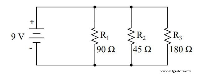
Analyzing Failures on a Simple Parallel Circuit
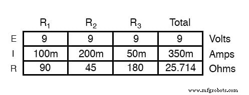
We apply the same before‑and‑after reasoning to parallel circuits. First, we establish the healthy baseline.
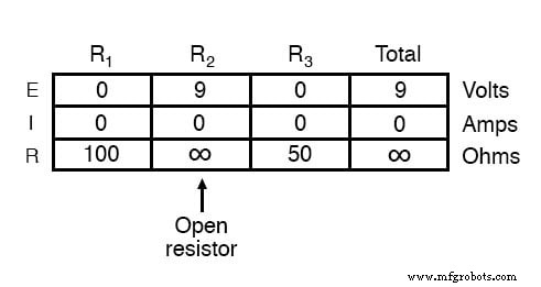
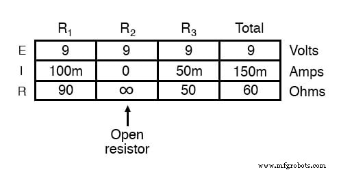
Opened Components in a Parallel Circuit
If R2 opens, only its branch current collapses; the total current decreases, but the voltage supplied by the source remains constant at 9 V. Because all branches share the same source voltage, the voltages across the remaining resistors stay unchanged, and their currents remain as before.
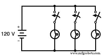
Household Lighting Application
This principle explains why, in a typical home wiring scheme, turning one lamp on or off does not affect the operation of others. Each lamp operates on its own branch, and only the branch current changes.
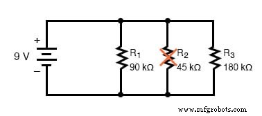
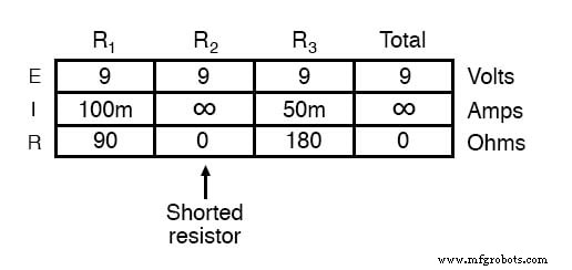
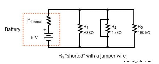
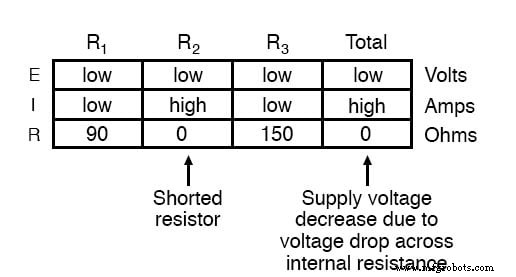
Shorted Components in a Parallel Circuit
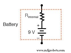
In an ideal scenario—perfect voltage source, zero‑resistance wires—a shorted resistor would theoretically draw infinite current. In reality, the voltage source cannot sustain infinite current, and its internal resistance becomes significant.
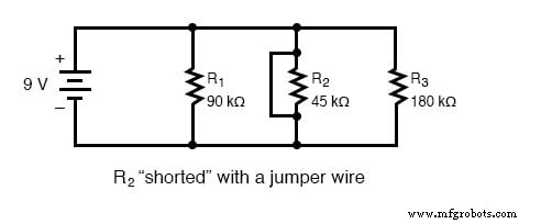
The internal resistance transforms the ideal parallel network into a series‑parallel combination. The shorted branch forces most of the supply voltage to drop across the source’s internal resistance, leaving almost no voltage for the other branches.
Direct short‑circuits across a voltage source can damage the source and are generally avoided unless the source is specifically designed to tolerate them.
Non‑ideal Assumptions in Analysis
The analysis above assumes the source maintains its rated voltage while supplying arbitrarily large currents—a unrealistic premise. Real sources have finite internal resistance that limits current and causes voltage sag.
While the internal resistance may be negligible for low‑current circuits, it dominates when short‑circuits generate high currents, underscoring the importance of accounting for it in practical troubleshooting.
Qualitative vs Quantitative Analysis
Later chapters will guide you through analyzing component failures without specific numerical values—qualitative analysis. This approach sharpens your intuition for circuit behavior, complementing the quantitative calculations you already know.
The skills developed here—drawing equivalent circuits, recalculating, and predicting outcomes—are essential for any electronics troubleshooter.
REVIEW:
- To determine what would happen in a circuit if a component fails, redraw the circuit with the equivalent resistance of the failed component and recalculate all values.
- Intuitive prediction of a circuit’s response to any fault is a crucial skill for electronics troubleshooting. The best way to learn is through hands‑on calculation and real‑world experiments, observing changes, constants, and the underlying reasons.
- A shorted component is one whose resistance has dramatically decreased.
- An open component is one whose resistance has dramatically increased. Resistors tend to fail open more often than shorted, and they almost never fail unless physically or electrically overstressed.
RELATED WORKSHEET:
- Basic Circuit Troubleshooting Worksheet
Industrial Technology
- Mastering AC Circuit Equations: Impedance, Reactance & Resonance
- Advanced Component Failure Analysis: Qualitative Techniques for Troubleshooting Complex Circuits
- Network Analysis Explained: Advanced Techniques for Complex Electrical Circuits
- Root Cause Failure Analysis: A Proven Approach for Manufacturing Excellence
- Comprehensive Failure Analysis: Preventing Equipment Loss and Reducing Costs
- Mastering Supernode Circuit Analysis: Step‑by‑Step Tutorial with Solved Example
- Mastering Supermesh Circuit Analysis: Step‑by‑Step Guide with Solved Example
- Master the Superposition Theorem: Step‑by‑Step Circuit Analysis with Practical Example
- Battery Desulfator Circuit: The Trusted Solution to Reverse Sulfation and Restore Battery Life
- Understanding Failure Analysis: Key Insights for Manufacturing Excellence