


Advanced Component Failure Analysis: Qualitative Techniques for Troubleshooting Complex Circuits
“I consider that I understand an equation when I can predict the properties of its solutions, without actually solving it.” —P.A.M. Dirac, physicist
Dirac’s insight translates beautifully to electrical engineering: a true engineer can anticipate how a circuit will behave when a component changes, without crunching numbers. In this post we extend that idea to a practical, qualitative failure‑analysis method that lets you troubleshoot any series‑parallel network quickly and confidently.
After covering the fundamentals of series and parallel circuits, we explored a purely qualitative approach—using symbols like ↑ (increase), ↓ (decrease), and – (unchanged) instead of exact figures. This technique builds intuition, speeds up troubleshooting, and eliminates arithmetic errors.
Applying the Method to a Real Circuit
Consider the complex network shown below. The diagram has been reduced to two parallel groups that are themselves in series.
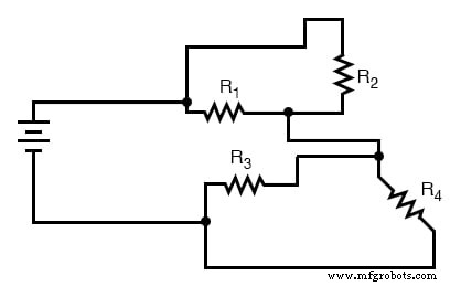
After simplification, the circuit looks like this:
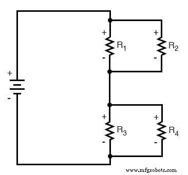
Here, R3 and R4 form a parallel pair, as do R1 and R2. The equivalent resistances of those pairs are then placed in series. In symbolic form:
RTotal = (R1//R2) + (R3//R4)
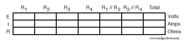
We start by laying out a table that lists every element—individual resistors, their parallel equivalents, the total resistance, the source voltage, and the currents through each branch.
Define the Failure Scenario
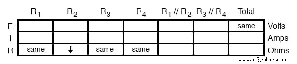
Suppose resistor R2 becomes shorted. All other components stay unchanged. Because we’re working qualitatively, we leave the table blank for now and will fill in only the symbols that describe change.
We use the word – to denote no change, ↑ for increase, and ↓ for decrease.
First, record the known values (the “givens”). Only R2 is different from its normal state:
Step 1 – Parallel Sections
The parallel pair R1//R2 will be affected because R2 has dropped to near zero resistance. A parallel combination that includes a near‑zero resistor drops in resistance, so we mark it ↓:
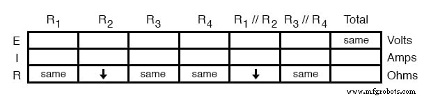
R3//R4 is untouched, so it remains –.
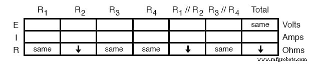
Step 2 – Total Resistance
When only one component changes, the total resistance shifts in the same direction. Since R2 decreased, the overall resistance decreases:
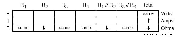
Step 3 – Total Current (Ohm’s Law, Qualitative)
With the source voltage fixed and total resistance lowered, Ohm’s Law tells us the total current will rise. We mark it ↑:
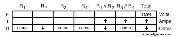
Step 4 – Current in Series Branches
Because the two parallel groups are in series, the same current flows through each. Thus, the currents through R1//R2 and R3//R4 both increase:
Step 5 – Voltages Across Parallel Sections
With total voltage unchanged but the current in the circuit rising, the voltage drop across R3//R4 must rise (E = IR). We therefore set that voltage to ↑:
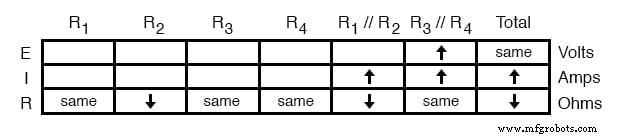
Because the sum of the two parallel voltages equals the battery voltage, the voltage across R1//R2 must fall:
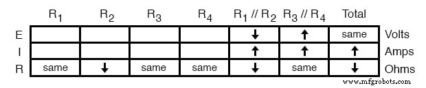
Step 6 – Voltages Across Individual Resistors
In a parallel pair, the voltage is the same across each member. Thus, the rise in R3//R4 propagates to R3 and R4, while the drop in R1//R2 propagates to R1 and R2:
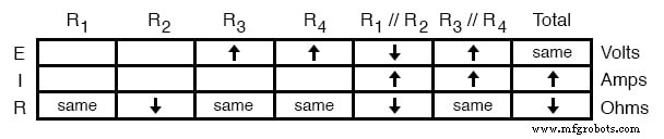
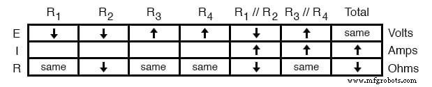
Step 7 – Currents Through Individual Resistors
Applying Ohm’s Law to the branches with unchanged resistance gives:
- Increased voltage across R3 and R4 → increased current (↑).
- Decreased voltage across R1 (unchanged resistance) → decreased current (↓).
For R2, both voltage and resistance drop, so we rely on the parallel‑current rule: the current in the R1//R2 branch is the sum of the currents in R1 and R2. Since the branch current rose and the R1 current fell, the R2 current must have risen to accommodate the difference.
With all cells filled, the qualitative table is complete, confirming the expected behavior: a shorted resistor lowers total resistance, increases overall current, and redistributes voltages and currents throughout the network.
Quick Reference Rules
- Single component failure → total resistance changes in the same direction.
- Shorted component → resistance ↓, current ↑, voltage may stay or drop.
- Open component → resistance ↑, current → 0, voltage may stay or rise.
These rules let you sketch a quick diagnostic map before measuring, saving time and reducing the chance of calculation errors.
RELATED WORKSHEETS:
- Series‑Parallel DC Circuits Worksheet
Industrial Technology
- AC Analysis Configuration: Curves, Points, and Frequency Sweep Settings
- Component Failure Analysis: Troubleshooting Techniques for Series and Parallel Circuits
- Root Cause Failure Analysis: A Proven Approach for Manufacturing Excellence
- RCM Blitz Analysis Estimating Tool – Plan Your Maintenance Investment Wisely
- Bearing Analysis: Diagnose Issues Early, Prevent Failures
- Selecting the Optimal Failure Analysis Technique for Reliable Equipment
- Comprehensive Failure Analysis: Preventing Equipment Loss and Reducing Costs
- Six Proven Ways to Eliminate Corrosion Failure Analysis Frustration
- Understanding Failure Analysis: Key Insights for Manufacturing Excellence
- Speaker Failure Analysis: Troubleshooting Manufacturing Issues