


Bearing Analysis: Diagnose Issues Early, Prevent Failures
Our goal is to cultivate a mindset that prioritizes problem detection and resolution over merely spotting failures. In practice, bearings often fail spectacularly, yet the vibration data that flagged the failure is rarely examined beyond the point of replacement. A structured, multi‑stage approach is essential: a vibration monitoring program must flag a problem at the earliest sign, and maintenance must act accordingly—sometimes by adjusting lubrication, sometimes by replacing a bearing. Timing the replacement is critical; premature changes may be perceived as a flaw in the system, while delayed action can damage other components and erase diagnostic evidence. Proactive maintenance, not reactive replacement, is the path to reliability.
The SKF Bearing Inspector decision‑support system accelerates, standardises, and improves the quality of bearing diagnostics. By aggregating foundational principles and practical engineering results on rolling‑bearing damage, it prevents recurring failures. Unlike traditional cause‑to‑symptom trees that can mislead, this tool models causality from conditions to observable symptoms, assigning probabilities that reflect real‑world uncertainties. State‑of‑the‑art computational intelligence underpins this approach, ensuring the diagnostics mirror the physics of bearing operation.
This article aligns with ISO 15243:2004, the benchmark for condition‑monitoring data analysis.
Understanding the Problem
Condition‑monitoring tools are most valuable when they help predict failures before they become critical. To leverage their full potential, you must first grasp the terminology and develop a strategy for data collection and conversion into actionable insight. Take a bearing example: did we merely detect a failure, or did we uncover the root cause and prevent recurrence? Vibration signatures can reveal load zones, mis‑alignment, and wear patterns that, if addressed early, save costly downtime.
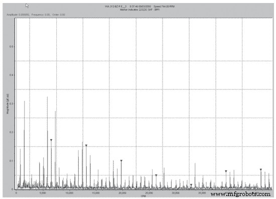
Figure 1. Enveloped Spectrum of the Bearing
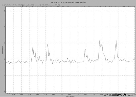
Figure 2. Waveform of the Bearing
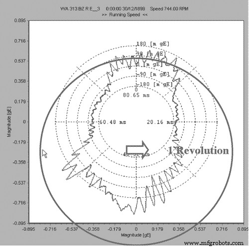
Figure 3. Cyclical Time Analysis of the Bearing
In this case, repeated failures led only to bearing replacements—an expensive and time‑consuming fix. By segmenting a data block to represent a single revolution and synchronously averaging it with a virtual trigger at 1 rpm, two distinct load zones emerged. These zones indicate impending stress on the inner race and cage, guiding corrective action. Subsequent journal inspection revealed ovalisation; machining corrected the fit, and the bearing has operated flawlessly since.
Root‑cause analysis combined with proactive maintenance proved decisive. The lesson: troubleshoot the problem, not just the failure.
Lubrication Management
When lubrication degrades, vibration, noise, or acoustic emissions typically rise. While auditory inspection can flag issues, the most reliable method is to trend vibration data against engineering units. Figure 4 illustrates a bearing’s vibration trend before, during, and after greasing.
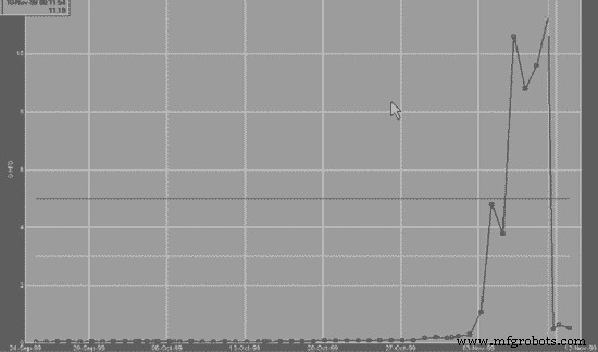
Figure 4. Vibration trend during lubrication
Although greasing appeared to resolve the problem, vibration levels never returned to pre‑issue levels. The residual increase stemmed from debris within the grease. A waveform captured during greasing (Figure 5) clearly shows how the greasing operation masked the underlying issue.
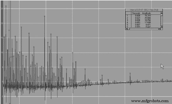
Figure 5. Waveform during greasing
Decision‑Support System for Bearing Failure Analysis
Accurate insight into rolling‑bearing damage is strategically vital for SKF and its customers. The SKF Bearing Inspector—a web‑enabled knowledge base—captures all available information, from fundamental principles to real‑world engineering outcomes. This enables rapid, consistent, high‑quality decision‑making and helps prevent recurrent damage.
Unlike early expert systems of the 1980s, which relied on rigid decision trees, the current system models causality from conditions to symptoms with quantified probabilities. This reflects the physical reality that a specific cause (e.g., incorrect mounting) manifests as observable damage (e.g., fretting), not vice versa.
Knowledge Representation
The system uses a probabilistic network that visually links nodes representing:
- Conditions: operating speed, load, bearing type, installation details, environment, etc.
- Internal Mechanisms: lubrication state, film breakdown, sliding contact.
- Failure Modes: subsurface fatigue, fretting corrosion, adhesive wear, etc.
- Observed Symptoms: discoloration, spalling, rust, pitting.
With roughly 150 nodes and 250 supporting images, the network embodies both expert knowledge and empirical data. Probabilities are calculated forward and backward, mirroring the diagnostic workflow of a clinician: generate hypotheses, then verify or reject them through targeted inspections.
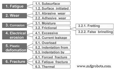
Figure 6. ISO 15243:2004
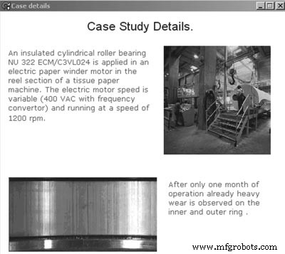
Figure 7.
Case Study: Electric Motor Bearing in a Paper Mill
Under “Typical Cases,” the Bearing Inspector showcases real‑world scenarios. One case involves a NU 322 ECM/C3VL024 insulated cylindrical roller bearing in a paper winder. Operating between 1,000 and 1,500 rpm, the bearing exhibited heavy wear on both inner and outer rings after just a month.
Loading the application data (Step 1) automatically populates the analysis. The tool initially flags high probabilities for false brinelling, adhesive wear, and current leakage. Guided by the software, the user checks for each failure mode’s specific symptoms:
- False brinelling—no shallow depressions found, so it is rejected.
- Adhesive wear—no characteristic signs present.
- Current leakage—small pitting observed on magnification, confirming the diagnosis.
Subsequent investigation uncovered an earthing fault in the winder construction, confirming the software’s recommendation.
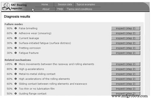
Figure 8. Step 1: Application conditions
Figure 9. Step 2: Initial diagnosis and confidence factors
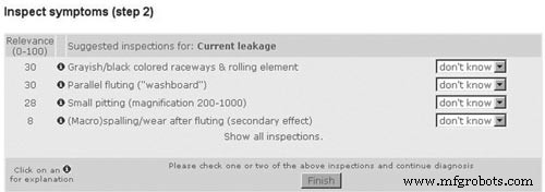
Figure 10. Step 3: Symptom inspection for current leakage
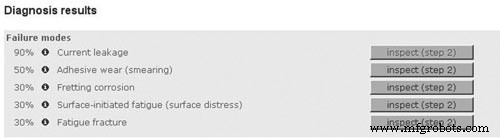
Figure 11. Final diagnosis and report generation
Rather than inspecting every possible symptom, the system prioritises the most discriminating observations based on the current hypothesis, reducing diagnostic effort. Users can export comprehensive reports in Word or HTML, complete with conditions, observations, and probability rankings.
Conclusion
The SKF Bearing Inspector delivers a fast, consistent, and high‑quality decision‑making process for bearing damage investigations. Accessible through a web interface, it empowers SKF engineers and customers to identify failure causes and implement preventive measures—ensuring that the same failure does not recur and guiding the configuration of vibration‑based condition‑monitoring programs.
Equipment Maintenance and Repair
- Understanding the NOT Gate (Inverter) in TTL Circuits
- Component Failure Analysis: Troubleshooting Techniques for Series and Parallel Circuits
- Advanced Component Failure Analysis: Qualitative Techniques for Troubleshooting Complex Circuits
- Choosing the Right Failure Analysis Tool: A Practical Guide for Reliability Professionals
- To Grease or Not to Grease: Best Practices for Electric Motor Bearing Lubrication
- Vibration Analysis Fundamentals: A Practical Guide for Predictive Maintenance
- Selecting the Optimal Failure Analysis Technique for Reliable Equipment
- The Three‑Barrier Solution: Enhancing Bearing Longevity in Harsh Environments
- Comprehensive Failure Analysis: Preventing Equipment Loss and Reducing Costs
- Understanding Failure Analysis: Key Insights for Manufacturing Excellence