


Building Series‑Parallel Resistor Circuits: From Breadboards to Terminal Strips
When designing battery‑powered resistor networks, beginners and seasoned hobbyists alike encounter multiple construction options. The most ubiquitous choice is the solderless breadboard—an inexpensive, reusable platform that lets you insert components and wires into a grid of interconnected nodes.
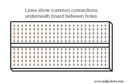
A breadboard may appear simple, but underneath each hole sits a spring‑clip that links to other clips below, forming a predictable, uniform connection matrix.
Series‑Parallel Circuit Construction on a Solderless Breadboard
Consider the following series‑parallel schematic:
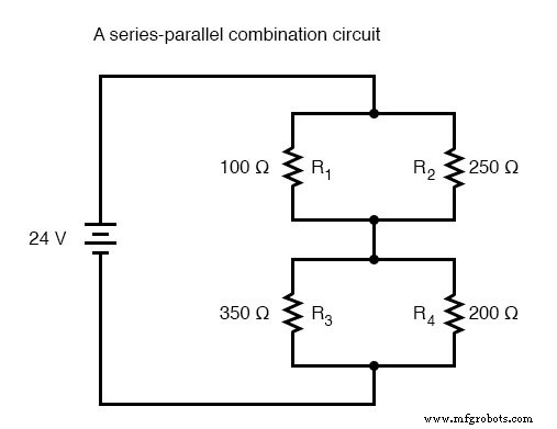
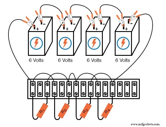
The recommended practice is to mirror the schematic layout on the breadboard for visual clarity. If the circuit requires 24 V and you only have 6 V batteries, connect four batteries in series:
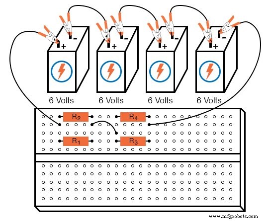
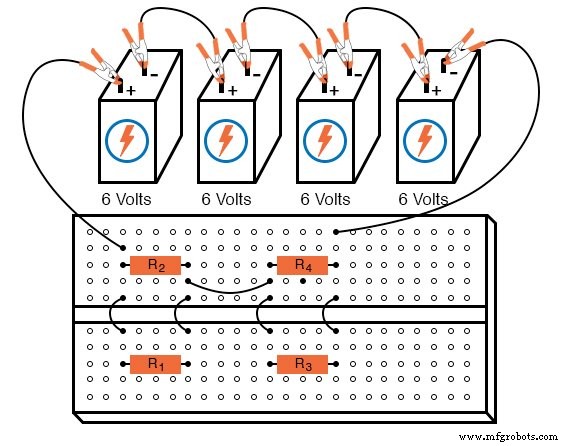
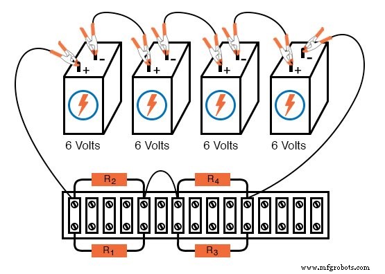
Alternative layouts are also viable. For instance, the same resistor network can be arranged differently on the same four batteries:
Series‑Parallel Circuit Construction on a Terminal Strip
When a more permanent solution is desired without soldering, a terminal strip (also known as a barrier strip or terminal block) offers a clean, mechanical method. Components are clamped by screws or heavy clips to metal bars mounted on an insulating body, ensuring electrical isolation between separate circuits.
Building on a terminal strip demands spatial reasoning, as the physical arrangement rarely matches the schematic. For example, the four‑resistor network can be assembled as follows:
Another layout, which preserves the schematic’s parallel grouping, attaches the two parallel resistor pairs to the same pair of terminal points:
Building More Complex Circuits on a Terminal Strip
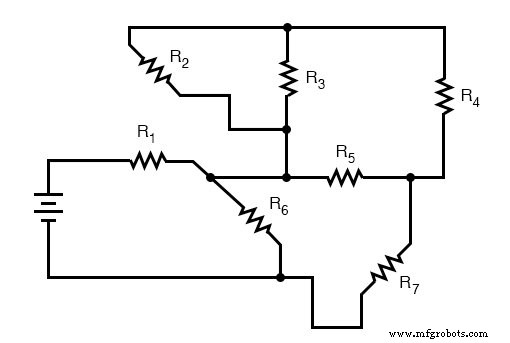
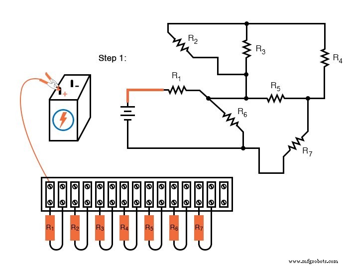
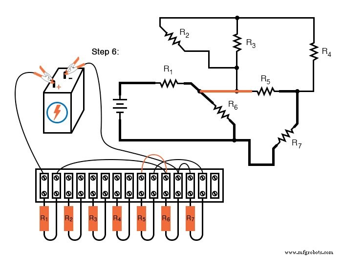
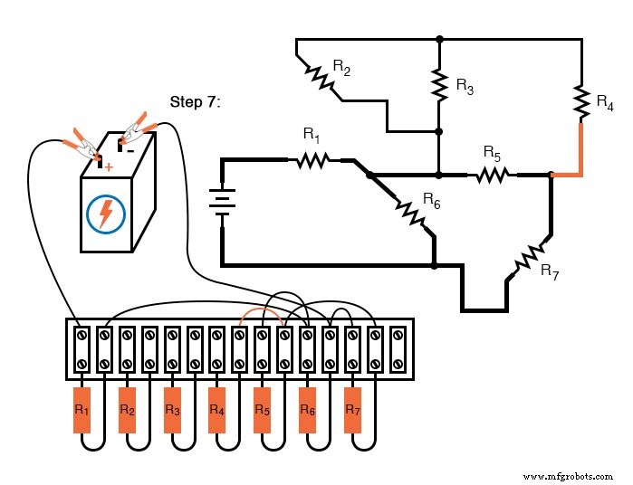
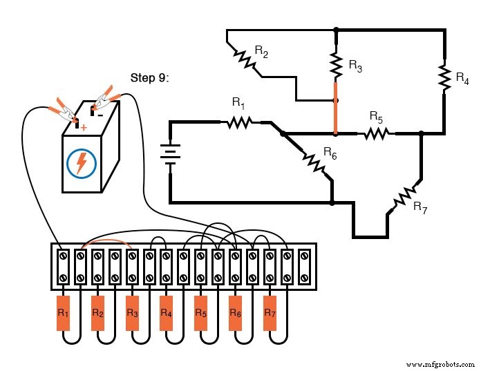
Complex arrangements require careful planning. The following example illustrates a circuit with seven resistors that can be replicated on a single terminal strip.
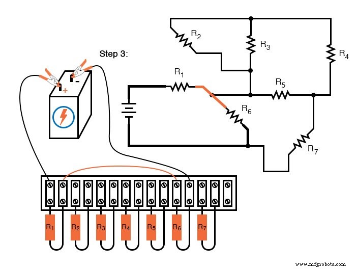
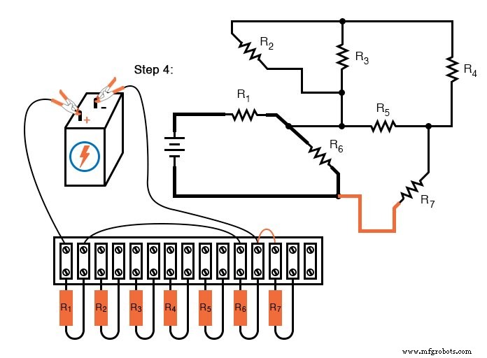
Although the strip contains only enough terminals to accommodate all components, a systematic approach guarantees an accurate build. Label each resistor, then connect wires one by one, verifying against the schematic after each step. The accompanying sequence of illustrations demonstrates this method.
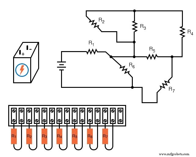
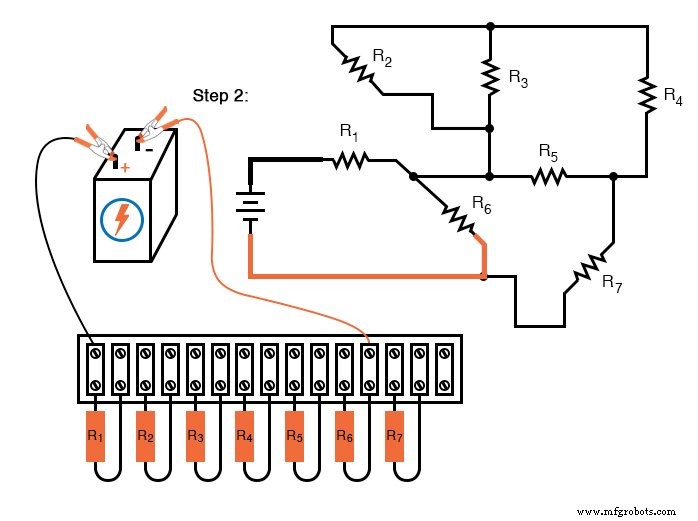
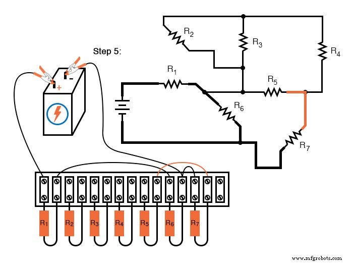
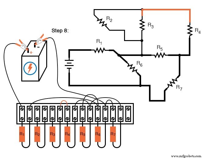
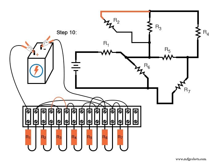
This layout faithfully reproduces the schematic’s electrical behavior while ensuring no single screw terminal is overloaded with more than two wire ends—a best practice that enhances reliability and ease of maintenance.
Variant Wire Connections and Human‑Centric Design
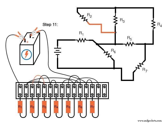
In step 11 of the example above, the final wire was added between the left terminals of R2 and R3 to complete the parallel connection. An alternative would be to route this wire from R2 to the right terminal of R1, which is electrically common with R3’s left terminal. Although this would still function, it would place three wires on a single terminal, creating a messy, potentially stress‑prone connection.
Another consideration is voltage polarity consistency. In the illustrated circuit, R7 shows a negative‑to‑positive orientation opposite to the rest. While electrically neutral, this can confuse users measuring voltage drops, especially with analog meters that invert scale on reversed polarity. Standardizing all resistor polarities simplifies troubleshooting and promotes clarity.
These examples underscore a key engineering principle: design choices that improve human readability—without compromising electrical performance—are essential for maintainable, robust circuits.
Review:
- Terminal‑strip assemblies are more permanent and modifiable than breadboards, though they require thoughtful layout.
- Avoid attaching more than two wire ends to a single terminal screw or clip.
- Prioritize clear, logical wiring when possible; it aids future modification and troubleshooting.
Related Worksheets:
- Series‑Parallel DC Circuits Worksheet
- Algebraic Equation Manipulation for Electric Circuits Worksheet
Industrial Technology
- Advanced Motor Control Circuits: Latching, Stop, and Time‑Delay Techniques
- Complementary NPN/PNP Audio Amplifier Circuit – Direct Coupling for Moderate Power
- Understanding Simple Series Circuits: Key Principles and Practical Examples
- Building Resistor Circuits: From Alligator Clips to PCBs
- Comprehensive Guide to Analyzing Series‑Parallel Resistor Networks
- Analyzing Complex RC Circuits Using Thevenin’s Theorem
- Fundamentals of AC Circuit Calculations: From Resistance to Kirchhoff’s Laws
- Understanding Instantaneous Values in Pure AC Resistor Circuits
- Parallel Resistor–Capacitor AC Circuits: Analysis, Impedance, and Ohm’s Law
- Impact of Resistance on Resonance in Series‑Parallel LC Circuits