


Parallel Resistor–Capacitor AC Circuits: Analysis, Impedance, and Ohm’s Law
Building on the series example, we now connect the same resistor and capacitor in parallel to observe how AC behavior changes.
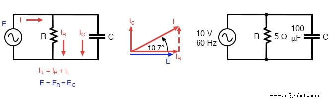
Parallel R‑C circuit.
Resistor and Capacitor in Parallel
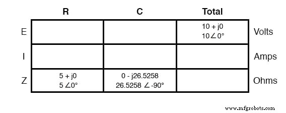
With the power source operating at the same frequency as in the series case, the resistor (R) and capacitor (C) retain identical resistance and capacitance values. Consequently, their individual impedances (Z) are also identical. We begin our analysis with the following table of given values:
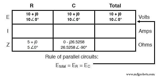
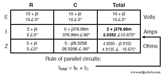
In a parallel topology, the voltage across each branch is equal, so the total source voltage (10 V∠0°) appears in every column:
Calculation Using Ohm’s Law
Applying Ohm’s Law (I = E/Z) vertically, we compute the branch currents for the resistor and capacitor:
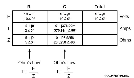
Just as in DC circuits, the branch currents in a parallel AC network sum to the total current, in accordance with Kirchhoff’s Current Law:
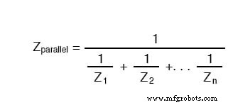
We can determine the total impedance by applying Ohm’s Law again (Z = E/I) to the “Total” column. The same reciprocal formula used for parallel resistances also applies to any parallel impedance configuration:
This relationship holds for all types of impedances—whether purely resistive, inductive, capacitive, or a mixture—because impedance behaves as a complex quantity in AC analysis.
While the reciprocal method may appear laborious without a calculator capable of handling complex arithmetic, both approaches—direct application of Ohm’s Law or the reciprocal formula—yield the same total impedance.
Key Takeaways
- Parallel impedances combine through the reciprocal formula: Z_total = 1/(1/Z1 + 1/Z2 + … + 1/Zn). Remember to use complex numbers, not scalars.
- Ohm’s Law in AC circuits remains: E = I·Z; I = E/Z; Z = E/I.
- When resistors and capacitors coexist in a parallel branch, the resulting total impedance has a phase angle between 0° and –90°, while the branch currents span 0° to +90°.
- Parallel AC circuits mirror the core principles of their DC counterparts: uniform voltage across all branches, additive branch currents, and impedance reduction via the reciprocal rule.
Related Resources
- Series and Parallel AC Circuits Worksheet
Industrial Technology
- Parallel Circuit Fundamentals: Voltage, Resistance, and Current Rules
- Advanced Motor Control Circuits: Latching, Stop, and Time‑Delay Techniques
- Complementary NPN/PNP Audio Amplifier Circuit – Direct Coupling for Moderate Power
- Understanding Series and Parallel Circuits: How They Work and Why They Matter
- Understanding Simple Series Circuits: Key Principles and Practical Examples
- Parallel Circuits Explained: Voltage, Current, and Resistance Principles
- Analyzing Complex RC Circuits Using Thevenin’s Theorem
- Fundamentals of AC Circuit Calculations: From Resistance to Kirchhoff’s Laws
- Analyzing Parallel Resistor–Inductor AC Circuits: A Practical Guide
- Series RC Circuit Analysis: Impedance, Phase Relationships, and SPICE Validation