


Impact of Resistance on Resonance in Series‑Parallel LC Circuits
In ideal LC networks with negligible resistance, the resonance frequency is governed solely by the inductor and capacitor values, yielding either infinite impedance in a parallel (tank) circuit or zero impedance in a series configuration. However, once significant resistance is introduced, the simple resonance condition no longer holds, and the actual resonant behavior shifts.
In the examples below we keep the capacitor at 10 µF and the inductor at 100 mH—the same values used in earlier calculations—while adding various resistive elements to observe how the resonance point moves.
Resonant Frequency of a High‑Resistance Circuit
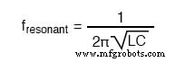
Our textbook equation predicts a resonance of 159.155 Hz. The following SPICE simulations show the frequency at which the current reaches its extremum when resistance is added.
Parallel LC circuit with a resistor in series with the inductor.
resonant circuit
 v1 1 0 ac 1 sin
 c1 1 0 10u
 r1 1 2 100
 l1 2 0 100m
 .ac lin 20 100 200
 .plot ac i(v1)
 .end
Result: The minimum current occurs at 136.8 Hz, a shift down from the calculated 159.2 Hz.
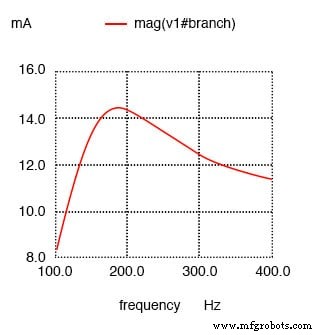
Adding a small series resistor (Rbogus) to the capacitor side avoids SPICE convergence issues and illustrates a different shift:
resonant circuit
 v1 1 0 ac 1 sin
 r1 1 2 100
 c1 2 0 10u
 rbogus 1 3 1e-12
 l1 3 0 100m
 .ac lin 20 100 400
 .plot ac i(v1)
 .end
Result: The minimum current now occurs at roughly 180 Hz, an upward shift.
Series LC Circuits with Parallel Resistance
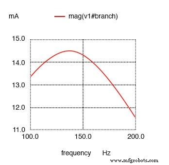
We now insert a significant resistor in parallel with either the inductor or the capacitor. A small 1 Ω resistor (R1) is also included in series to limit the overall current at resonance.
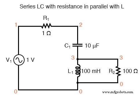
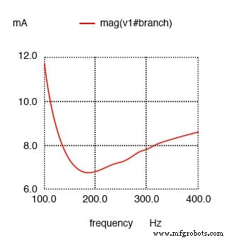
Series LC with a 100 Ω resistor in parallel with the inductor.
resonant circuit
 v1 1 0 ac 1 sin
 r1 1 2 1
 c1 2 3 10u
 l1 3 0 100m
 r2 3 0 100
 .ac lin 20 100 400
 .plot ac i(v1)
 .end
Result: The current peak moves to approximately 178.9 Hz, an upward shift.
With the 100 Ω resistor placed in parallel with the capacitor:
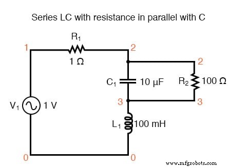
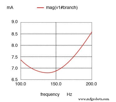
Series LC with a 100 Ω resistor in parallel with the capacitor.
resonant circuit
 v1 1 0 ac 1 sin
 r1 1 2 1
 c1 2 3 10u
 r2 2 3 100
 l1 3 0 100m
 .ac lin 20 100 200
 .plot ac i(v1)
 .end
Result: The maximum current now appears at 136.8 Hz, a downward shift.
Understanding Antiresonance
The systematic shift of resonance caused by added resistance is known as antiresonance. The pattern observed in the four SPICE examples is consistent:
- Parallel LC (tank):
• R in series with L → frequency down
• R in series with C → frequency up - Series LC:
• R in parallel with L → frequency up
• R in parallel with C → frequency down
Because of the complementary roles of inductors and capacitors, resistance in series with one element produces the same shift as resistance in parallel with the other. The magnitude of the shift is identical, and the impedance plots are mirror images.
The Skin Effect
Real inductors contain significant resistance due to their long windings. This resistance increases with frequency because of the skin effect—AC current tends to flow near the conductor’s surface, reducing the effective cross‑sectional area and thus raising resistance.
Core Losses in Iron‑Core Inductors
Another source of resistance is the generation of eddy currents within the iron core when the magnetic flux changes. These “core losses” behave like an additional resistive load, which can be mitigated by laminated cores and high‑grade magnetic materials but cannot be entirely eliminated.
RLC Circuits
When all three elements—resistor, inductor, and capacitor—are connected in series, the resonance frequency remains unchanged even if the series resistance is large. The SPICE result confirms this:
Series RLC: resonance at 159.2 Hz; increased resistance only broadens the peak.
series rlc circuit
 v1 1 0 ac 1 sin
 r1 1 2 100
 c1 2 3 10u
 l1 3 0 100m
 .ac lin 20 100 200
 .plot ac i(v1)
 .end
Result: The current maximum remains at 159.2 Hz, confirming that resonance is preserved.
Antiresonance’s Dampening Effect
In a lossless tank circuit, the energy oscillates indefinitely, much like a frictionless pendulum. Real circuits, however, suffer energy losses from resistance, core losses, or radiation, causing the oscillation to decay. Antiresonance can be deliberately introduced to damp unwanted oscillations, for example, by adding a resistor in parallel with stray capacitance.
Consider an L/R time‑delay circuit:
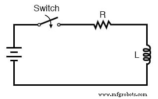
When the switch closes, the inductor charges with a time constant of L/R. In practice, stray capacitance between the coil windings and the surrounding circuitry can produce ringing. Adding sufficient resistance produces antiresonance, dissipating energy and preventing prolonged oscillations.
The same principle applies in mechanical systems—shock absorbers in vehicles dissipate kinetic energy to suppress resonant vibrations.
Review
- Added resistance can shift resonance—this phenomenon is called antiresonance.
- Inductor resistance rises with frequency due to the skin effect, and iron‑core inductors also suffer core‑loss resistance.
- In a true series RLC circuit, resonance remains at the frequency predicted by L and C; resistance only affects bandwidth.
Related Worksheets
- Resonance Worksheet
Industrial Technology
- Advanced Motor Control Circuits: Latching, Stop, and Time‑Delay Techniques
- Complementary NPN/PNP Audio Amplifier Circuit – Direct Coupling for Moderate Power
- Understanding Simple Series Circuits: Key Principles and Practical Examples
- Understanding Series-Parallel Circuits: How They Work & Why They Matter
- Building Series‑Parallel Resistor Circuits: From Breadboards to Terminal Strips
- Analyzing Complex RC Circuits Using Thevenin’s Theorem
- Fundamentals of AC Circuit Calculations: From Resistance to Kirchhoff’s Laws
- Series RC Circuit Analysis: Impedance, Phase Relationships, and SPICE Validation
- Parallel Resistor–Capacitor AC Circuits: Analysis, Impedance, and Ohm’s Law
- Practical Applications of Resonance in AC Circuits