


Building Resistor Circuits: From Alligator Clips to PCBs
Mastering basic circuit construction is essential for anyone studying electricity. Whether you’re assembling a simple single‑battery, single‑resistor setup or designing a multi‑component prototype, the right tools and techniques can streamline the process and enhance reliability.
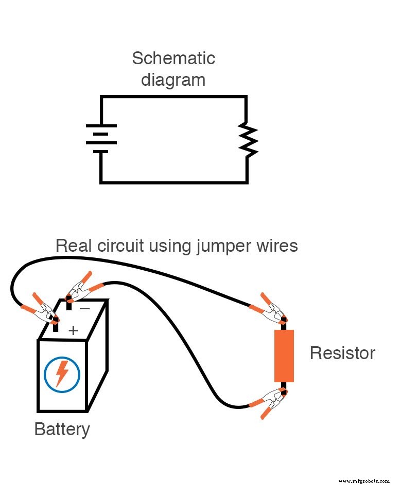
Using Alligator Clip Jumper Wires for Simple Circuits
For a straightforward series circuit with one battery and a single resistor, alligator‑clip jumper wires offer a safe, quick, and reusable connection method:
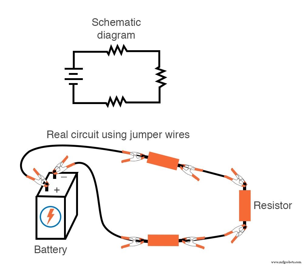
When expanding to a series chain of three resistors, the same point‑to‑point approach remains effective:
Constructing More Complex Circuits with a Solderless Breadboard
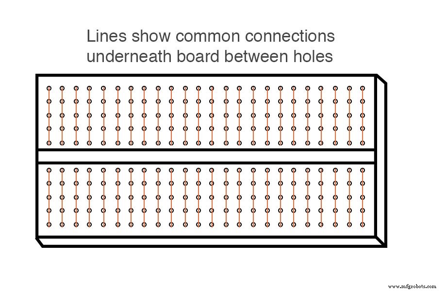
For circuits that grow beyond a handful of components, a solderless breadboard provides a flexible, semi‑permanent platform. Its plastic body contains rows of spring‑loaded metal clips that capture component leads and wires, automatically connecting every fifth hole in a vertical column.
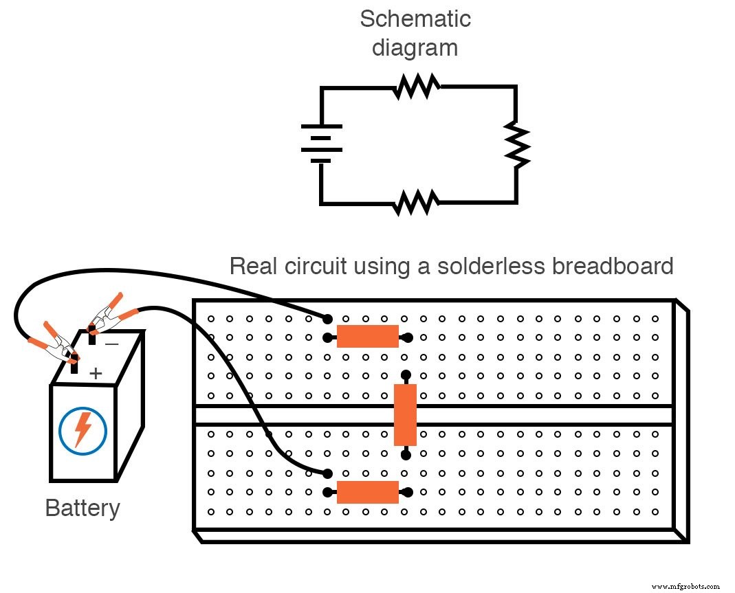
Illustration of the internal connection pattern:
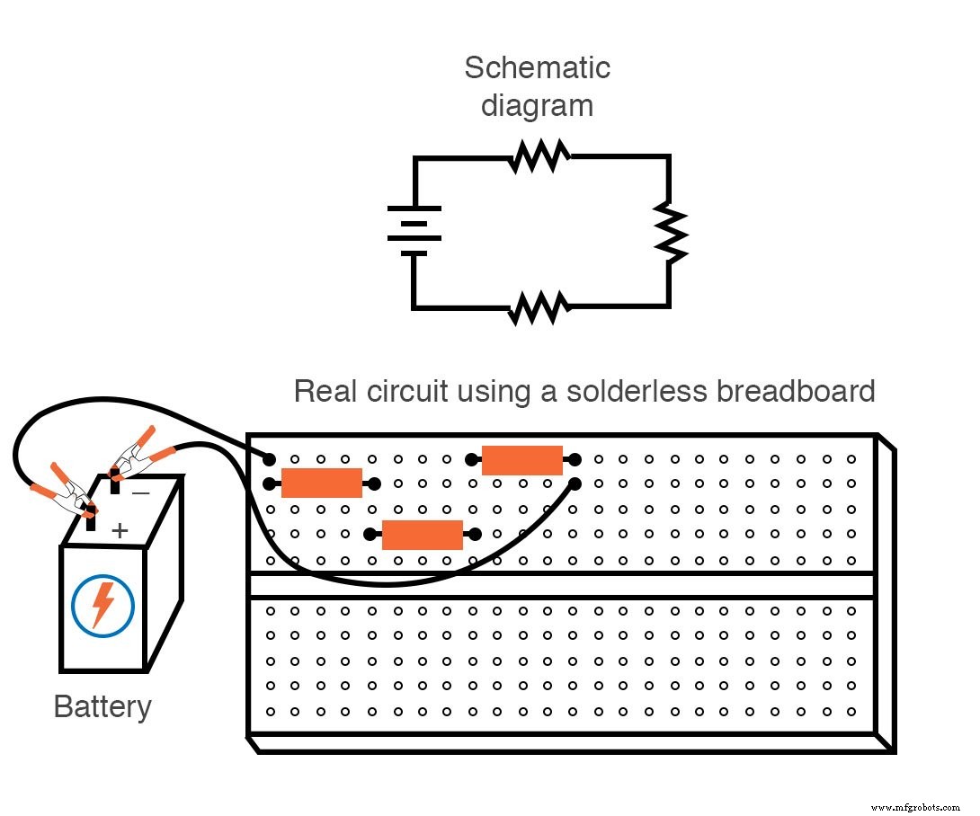
Series Circuit on a Breadboard
Using the same three‑resistor example, the breadboard configuration is as follows:
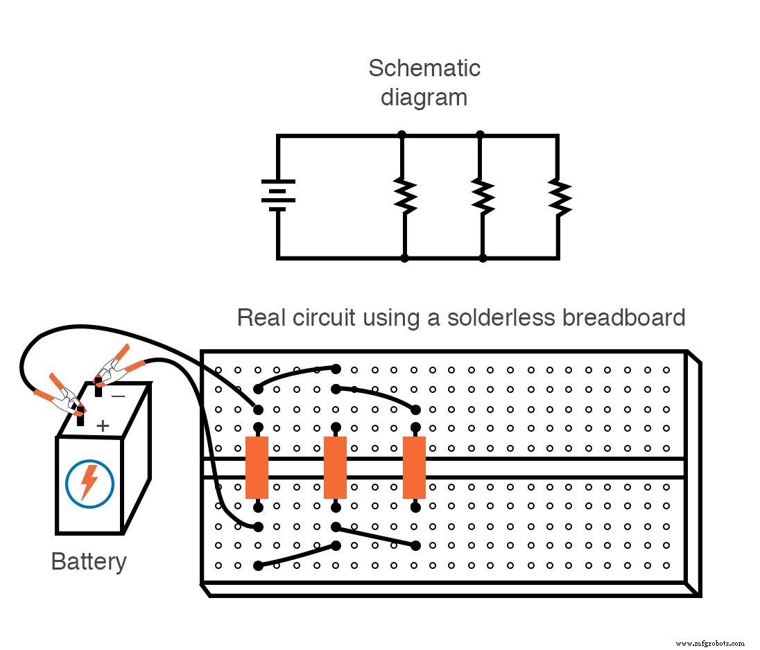
Parallel Circuit on a Breadboard
Parallel arrangements are equally straightforward:
Limitations of Breadboards
- Designed for temporary use; components can loosen if the board is moved or shaken.
- Typical current limit is below 1 A; higher currents may overheat the spring clips.
Soldering and Wire‑Wrapping for Permanent Builds
When a circuit needs to withstand repeated handling or operate under higher currents, soldering or wire‑wrapping offers a durable solution. Both techniques secure components to a rigid substrate (often phenolic or fiberglass) before joining leads with either melted alloy or tightly wrapped gauge wire.
Printed Circuit Boards (PCBs) for Hobbyists
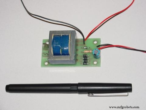
PCBs provide pre‑etched copper traces that replace manual jumper wires. A typical hobbyist board features isolated copper pads around each hole, enabling independent connections. Commercial PCBs also include signal and power traces for more complex designs, such as the 120 V AC to low‑voltage DC power supply illustrated below.
Board with trace layout and component placement:
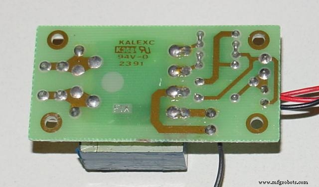
View of the underside shows soldered connections and trace pathways:
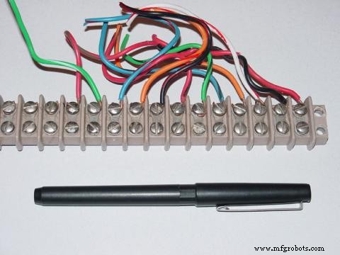
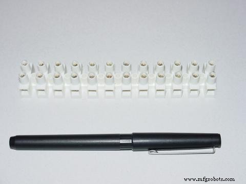
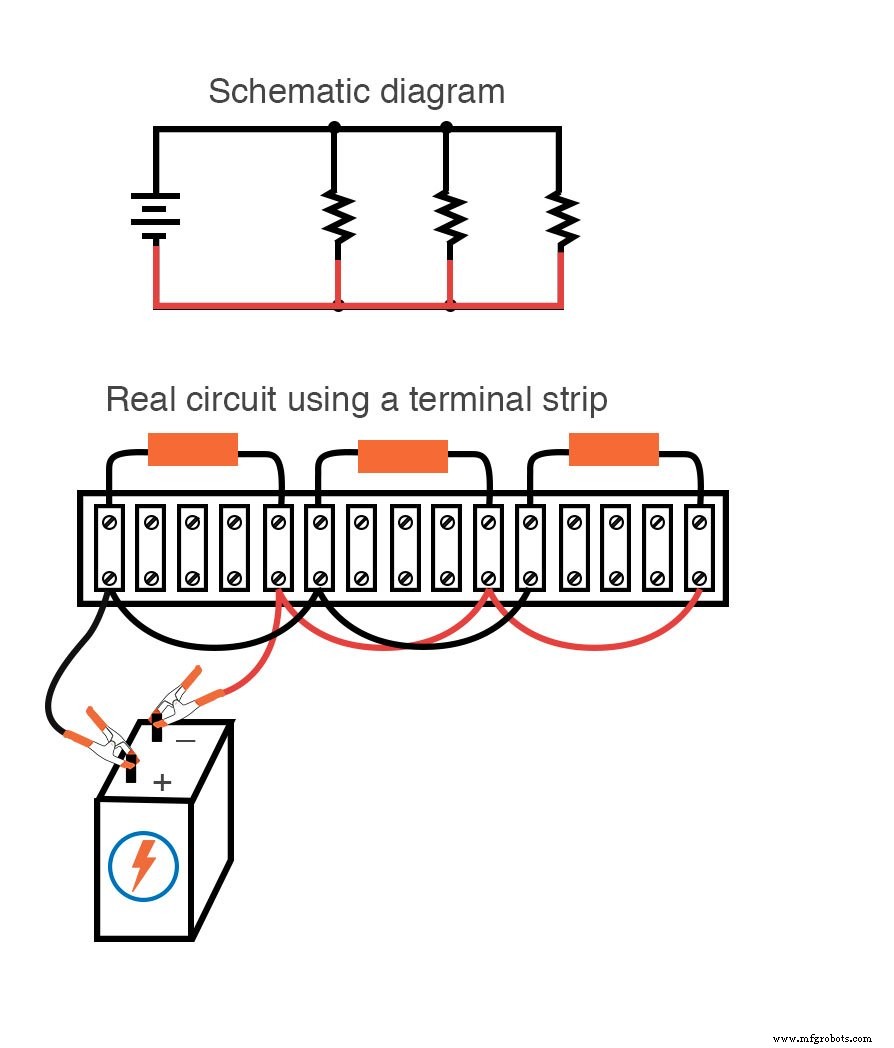
Terminal Strips – Industrial‑Grade Connection Solutions
Terminal strips, also known as barrier strips or terminal blocks, consist of a non‑conductive body with embedded metal bars. Each bar is secured by a screw or spring clip, allowing wires or component leads to be fastened with a simple screwdriver.
Common styles include standard and “European” recessed‑screw designs to prevent accidental shorts.
Building a Circuit on a Terminal Strip
Here is a single‑battery, three‑resistor series circuit assembled on a terminal strip:
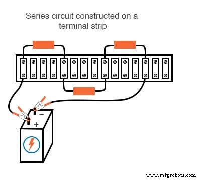
Terminal strips combine the robustness of industrial wiring with the simplicity of a screwdriver‑based connection, making them suitable for both temporary prototyping and permanent installations.
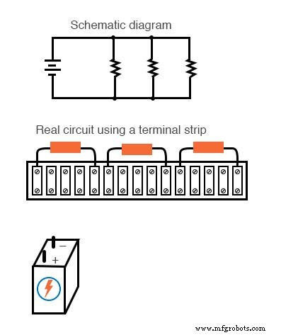
Translating a Schematic Diagram to Physical Layout
Converting a schematic into a real circuit demands spatial reasoning and careful wire planning. While schematics prioritize readability, actual construction often requires repositioning components to accommodate layout constraints.
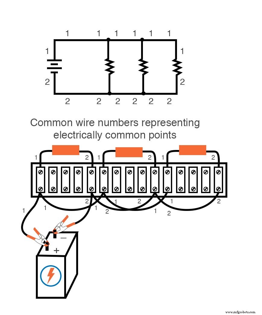
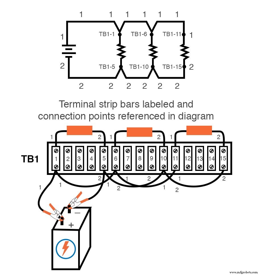
Step‑by‑Step Example: Parallel Resistor Circuit on a Terminal Strip
1. Begin with a clean schematic and secure all components on the strip, leaving wires unconnected.
2. Follow each schematic wire, adding real connections between the corresponding points. Use an additional line on the schematic to mark completed links.
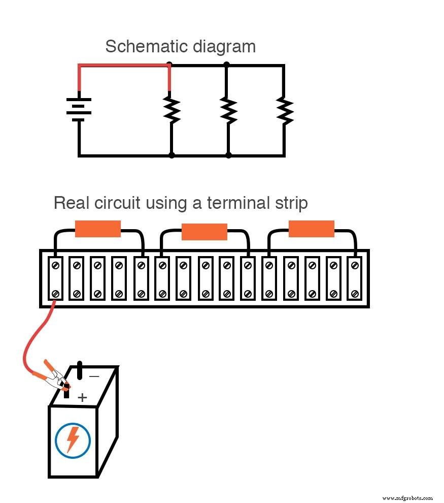
3. Group common nodes (e.g., the top of all resistors) and connect them together before proceeding to the next node.
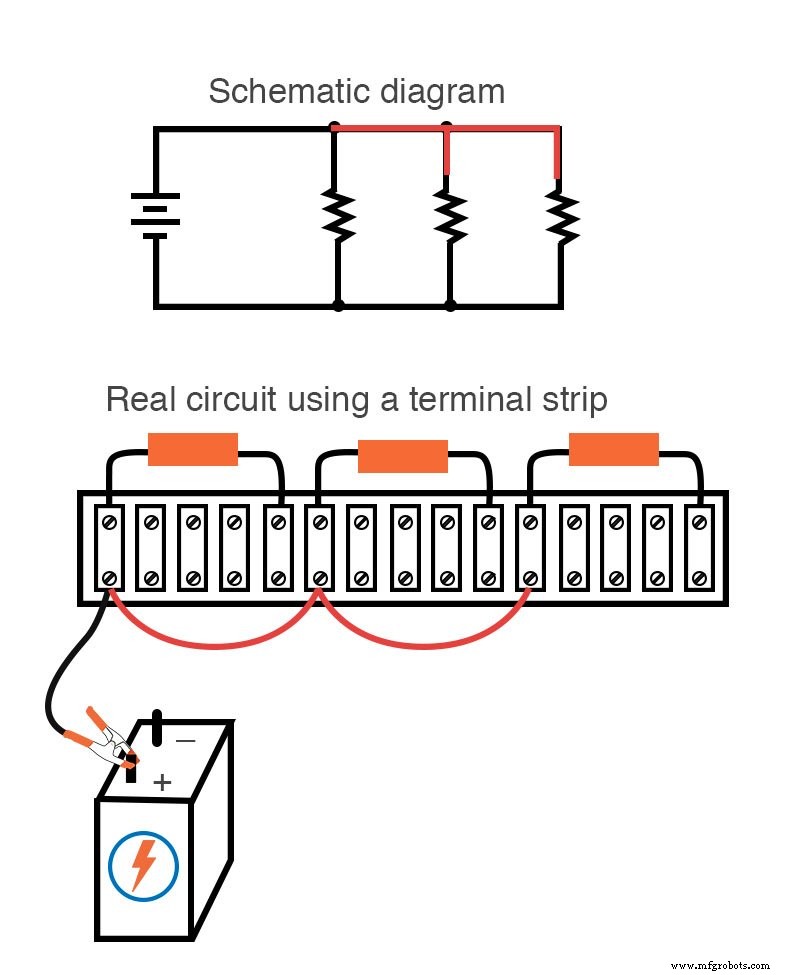
4. Finally, connect the remaining nodes to the opposite battery terminal.
5. Label wires and terminals consistently. Industry practice often uses numerical tags (e.g., wire 1, wire 2) and a terminal block identifier (TB‑1, TB‑2) to keep complex layouts organized.
Best Practices for Wiring and Labeling
- Label all wires and nodes to reduce assembly errors.
- Use color‑coded or numbered tags for quick identification.
- Maintain a master schematic that reflects the final layout, updating it as changes occur.
Key Takeaways
- A solderless breadboard excels at rapid prototyping of temporary circuits.
- Soldering provides reliable, permanent connections, ideal for high‑current or long‑term projects.
- Wire‑wrapping offers a solder‑free alternative that still delivers solid mechanical and electrical joints.
- Terminal strips combine industrial robustness with easy installation, suitable for both temporary and permanent setups.
Related Worksheets
- Ohm’s Law Practice Worksheet With Answers Worksheet
- Series DC Circuits Practice Worksheet with Answers Worksheet
- Series‑Parallel DC Circuits Worksheet
Industrial Technology
- Building and Troubleshooting a Basic 6‑V Battery‑Lamp Circuit
- Advanced Motor Control Circuits: Latching, Stop, and Time‑Delay Techniques
- Complementary NPN/PNP Audio Amplifier Circuit – Direct Coupling for Moderate Power
- Understanding Simple Series Circuits: Key Principles and Practical Examples
- Parallel Circuits Explained: Voltage, Current, and Resistance Principles
- Comprehensive Guide to Analyzing Series‑Parallel Resistor Networks
- Building Series‑Parallel Resistor Circuits: From Breadboards to Terminal Strips
- Analyzing Complex RC Circuits Using Thevenin’s Theorem
- Fundamentals of AC Circuit Calculations: From Resistance to Kirchhoff’s Laws
- Understanding Breadboards: How They Work & Why They're Essential for Prototyping Electric Circuits