


Testing Diode Polarity and Forward Voltage with a Multimeter
Understanding Diode Polarity
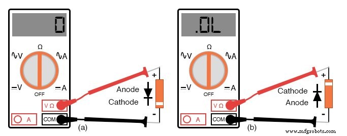
Accurately identifying the cathode and anode of a diode is essential for every electronics hobbyist and technician. A diode functions as a one‑way valve for current, and a simple DC ohmmeter can confirm this behavior. When the meter leads are connected in the forward direction, the device should display a low resistance. Reversing the leads should yield a very high resistance (often shown as “OL” on digital meters).
Polarity determination:
- Low resistance → forward bias; the red lead is the anode and the black lead is the cathode (most meters).
- High resistance → reverse bias.
Using a Multimeter to Find Polarity
Identifying the Test Leads
Before testing, confirm which probe is positive (+) and which is negative (−) when the meter is set to the resistance (Ω) function. In most digital multimeters, the red lead is positive and the black lead is negative, following standard electronics color coding. However, some analog meters invert this convention, making the black lead positive and the red lead negative when measuring resistance. Always verify your meter’s wiring to avoid confusion.
Limitations of the Ohmmeter Function
Using an ohmmeter to check a diode provides only a qualitative result. A reading of 1.73 Ω, for example, does not represent the diode’s forward voltage drop or its intrinsic resistance; it depends on the meter’s internal current and the diode’s characteristics. Therefore, an ohmmeter is useful only for confirming that the diode conducts in one direction and blocks in the other.
Diode Check Mode in Digital Multimeters
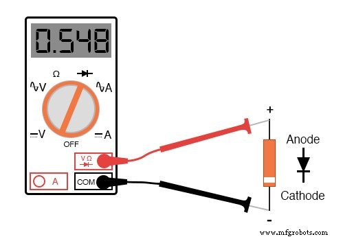
Many modern digital multimeters include a dedicated “diode check” function. This mode applies a small test current and measures the voltage drop across the diode, displaying the forward voltage in volts instead of resistance. The meter typically shows a forward drop of around 0.548 V for a silicon diode, slightly lower than the nominal 0.7 V because of the low test current.
Measuring Forward Voltage Without a Dedicated Function
If your meter lacks a diode‑check mode, you can construct a simple test circuit:
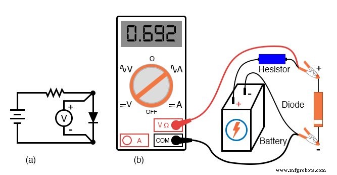
This circuit uses a battery, a series resistor, and a voltmeter. When the diode is forward biased, the voltmeter reads the forward voltage. If the diode is connected in reverse, the voltmeter reads the full battery voltage.
Such a setup can also serve as a temperature sensor: the voltage across the diode is inversely proportional to its junction temperature. To avoid self‑heating, keep the test current low.
Considerations When Using the Resistance Function
Some multimeters output a very low test voltage (below 0.3 V) in the resistance mode. This keeps the PN junction from becoming forward biased, allowing accurate measurement of non‑semiconductor components even when connected to a diode. However, if you test a diode in this mode, the meter may display a high resistance (megaohms) even when the leads are correctly aligned, because the low voltage fails to forward bias the junction.
When measuring a resistor in parallel with a diode, the low test voltage ensures the diode appears as an open circuit, enabling a true resistance reading. Conversely, an ohmmeter that cannot forward‑bias a diode will show a high resistance for the diode itself.
Testing reverse voltage is more challenging, as exceeding the diode’s peak inverse voltage (PIV) can destroy it. Zener diodes, designed to break down in reverse bias without damage, can be tested with a higher voltage source, resistor, and voltmeter to verify their breakdown voltage.
Key Takeaways
- Use an ohmmeter for a quick qualitative check of diode polarity: low resistance forward, high resistance reverse.
- Always verify which probe is positive and negative; color coding may vary.
- Many multimeters provide a diode‑check function that displays the forward voltage drop directly.
- For accurate forward voltage measurement, especially at higher currents, construct a test circuit with a battery, resistor, and voltmeter.
- Low‑voltage resistance mode can isolate diodes from parallel measurements but will show them as open circuits.
Related Worksheets
- Basic Oscilloscope Operation Worksheet
Industrial Technology
- Mastering Ohmmeter Measurements: A Practical Guide to Resistance Testing
- Exploring Nonlinear Resistance in Incandescent Lamps: A Practical Lab Guide
- Commutating Diode Experiment: Suppressing Inductive Kickback with a Neon Lamp
- Voltage Regulator Experiment with a 12‑Volt Zener Diode
- Diodes: Fundamentals, Construction, and Applications
- How to Identify and Test a Bipolar Junction Transistor (BJT) with a Multimeter
- Accurate Multimeter Testing of JFET Continuity and Pin‑Off Behavior
- Resistors: Fundamentals, Types, and Practical Applications
- Understanding Conductance: The Inverse of Resistance
- Calculating Wire Resistance for Voltage‑Drop‑Critical Circuits