


Commutating Diode Experiment: Suppressing Inductive Kickback with a Neon Lamp
Parts and Materials
- 6 V battery
- Power transformer: 120 VAC step‑down to 12 VAC (Radio Shack catalog # 273‑1365, 273‑1352, or 273‑1511)
- 1N4001 rectifying diode (Radio Shack catalog # 276‑1101) – any 1N400X series diode will work
- Neon lamp (Radio Shack catalog # 272‑1102)
- Two SPST toggle switches (Single‑Pole, Single‑Throw)
While a dedicated transformer is recommended, any iron‑core inductor will suffice. For cost‑effective construction, household light switches can serve as the toggle switches.
Cross‑References
- Lessons In Electric Circuits, Vol. 1, Chap. 16: “RC and L/R Time Constants”
- Lessons In Electric Circuits, Vol. 3, Chap. 3: “Diodes and Rectifiers”
Learning Objectives
- Review the phenomenon of inductive “kickback”
- Demonstrate how a diode can suppress inductive kickback
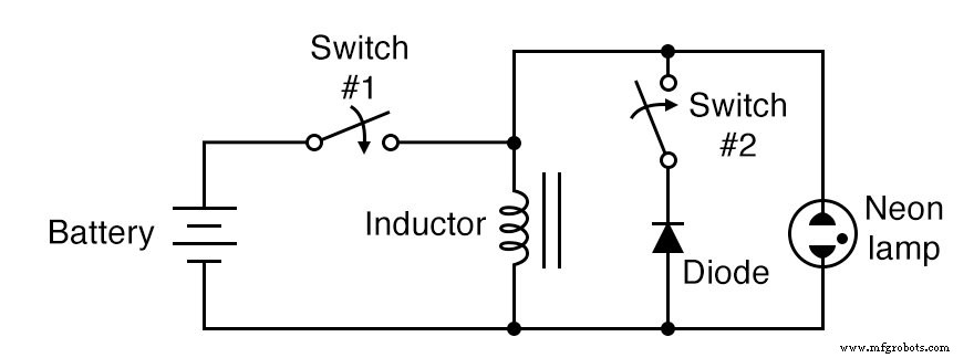
Schematic Diagram
Illustration
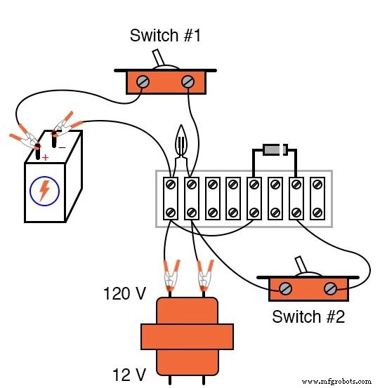
Instructions
When assembling the circuit, observe the diode’s polarity: the cathode (marked with a single band) must face the positive (+) terminal of the battery. The diode should be reverse‑biased and non‑conducting when switch #1 is in the “on” position.
Use the high‑voltage (120 V) winding of the transformer as the inductor coil. The primary winding typically has greater inductance than the secondary, producing a more pronounced lamp‑flashing effect. With switch #2 set to “off”, the diode is disconnected from the circuit.
Open and close switch #1 quickly. When it opens, the neon lamp will flash due to inductive kickback: the inductor generates a large voltage as it resists the sudden drop in current. This flash demonstrates the energy stored in the magnetic field.
Inductive kickback can damage switch contacts through arcing. The neon lamp provides a safe discharge path, converting the stored energy into light and heat, thereby protecting the contacts.
To illustrate the protective effect, close switch #2 to connect the diode. Repeat the rapid open/close of switch #1. This time, the neon lamp will not flash because the diode clamps the voltage spike, redirecting the current safely.
Verify the circuit operation by measuring the voltage across the inductor while switch #1 is closed. A full battery voltage indicates correct diode orientation; a low reading suggests a reversed diode causing a short.
Related Worksheet
- Miscellaneous Diode Applications Worksheet
Industrial Technology
- Circuit With a Switch: A Practical Guide to Basic Electrical Circuits
- Voltage Regulator Experiment with a 12‑Volt Zener Diode
- Diodes: Fundamentals, Construction, and Applications
- Understanding Electrical Switches: Types, Functions, and Applications
- Eliminating Contact Bounce in Mechanical Switches
- Comprehensive Guide to Diode Ratings & Datasheet Parameters
- Understanding Clipper Circuits: Theory, Simulation, and Practical Applications
- Multimeters: From Analog to Digital – A Comprehensive Guide
- Mastering the C# Switch Statement: Syntax, Examples & Best Practices
- Professional Wiring Guide for Combo Switch/Outlet Devices – Diagrams & Installation Tips