


Half‑Wave Rectifier Experiment: Build, Measure, and Simulate a Simple AC‑to‑DC Motor Circuit
Overview
In this hands‑on laboratory you will construct a half‑wave rectifier that converts a low‑voltage AC supply into a DC‑biased signal to drive a small permanent‑magnet motor. You will learn how to measure the resulting DC bias and ripple voltage, listen to the ripple with an audio detector, and verify the behavior with a SPICE simulation.
Parts and Materials
- Low‑voltage AC power supply (6‑volt output)
- 6‑volt battery
- One 1N4001 rectifying diode (or any 1N400X series diode)
- Small hobby motor, permanent‑magnet type (e.g., Radio Shack #273‑223)
- Audio detector with headphones
- 0.1 µF coupling capacitor (e.g., Radio Shack #272‑135)
The 0.1 µF capacitor couples the audio detector to the circuit so that only AC reaches the detector. The exact value is not critical; we have used 0.27 µF to 0.015 µF successfully. A lower value attenuates low‑frequency content, reducing headphone volume, so choose a higher value if the tone is faint.
Cross‑References
Lessons In Electric Circuits, Volume 3, chapter 3: “Diodes and Rectifiers”.
Learning Objectives
- Understand the role of a diode as a rectifier
- Compare motor operation on AC versus DC power
- Measure ripple voltage with a digital voltmeter
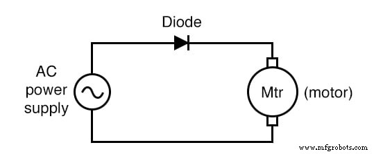
Schematic Diagram
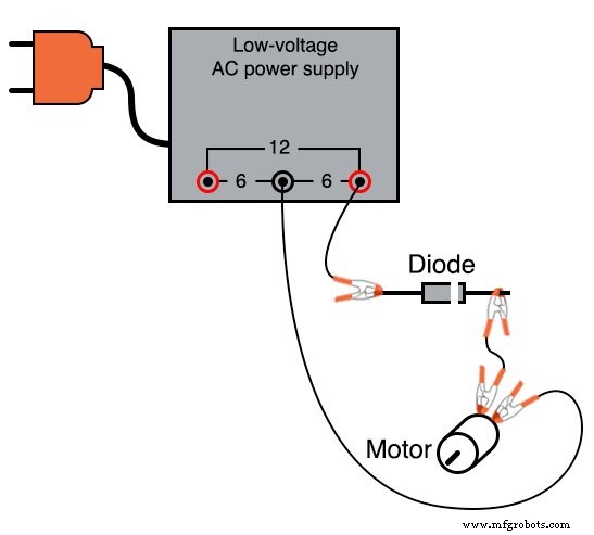
Illustration
Instructions
1. Connect the motor to the 6‑volt AC supply through the rectifying diode as shown in the schematic. The diode passes current only during the positive half‑cycle, producing a pulsating DC that drives the motor in one direction.
2. Momentarily short the motor terminals with a jumper wire to observe the effect of allowing the full AC waveform to reach the motor. The motor will stall or run poorly.
3. Remove the jumper and reverse the diode’s orientation. Observe the change in motor behavior; the motor should now run smoothly in the opposite direction.
4. Measure the DC voltage across the motor terminals with the voltmeter set to DC. This reading reflects the average bias of the half‑wave rectified signal.
5. Re‑set the meter to AC to measure the ripple voltage. The reading represents the superimposed AC component riding on the DC bias. Typical values for a 6‑volt source with a 10 kΩ load are around 3–4 V peak‑to‑peak.
6. Compare these readings with those taken when the motor is powered by a 6‑volt battery. The battery should produce a nearly pure DC voltage with negligible ripple; any measured AC will be due to the motor’s commutator action.
Listening to Ripple with an Audio Detector
Turn the detector sensitivity to a low setting and connect it across the motor terminals through a 0.1 µF capacitor. The capacitor acts as a high‑pass filter, blocking DC and allowing you to hear the AC ripple.
With a battery, the detector will emit a high‑pitched buzz. Replacing the battery with the AC supply and rectifier will lower the pitch, reflecting the half‑wave nature of the rectified signal.
Computer Simulation
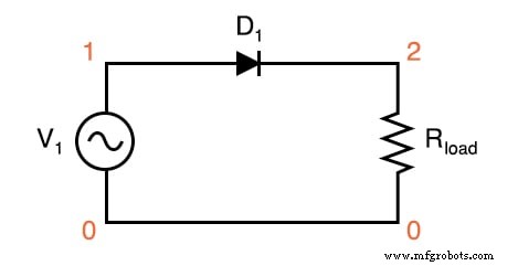
Schematic with SPICE node numbers:
Netlist (copy the following into a text file):
Halfwave rectifier v1 1 0 sin(0 8.485 60 0 0) rload 2 0 10k d1 1 2 mod1 .model mod1 d .tran .5m 25m .plot tran v(1,0) v(2,0) .end
The simulation shows the input sine wave and the output as a series of positive “humps.” The AC source is specified as 8.485 V peak to match a 6‑V RMS sine wave.
Related Worksheet
- Precise Diode Circuits Worksheet
Industrial Technology
- Using a Potentiometer as a Rheostat for Simple Motor Speed Control
- Build a Permanent Capacitor Split-Phase Induction Motor – Step‑by‑Step Guide
- Build a Large-Scale AC Permanent Split‑Capacitor Induction Motor
- Full-Wave Bridge Rectifier: Design, Benefits, and Practical Implementation
- Full‑Wave Center‑Tap Rectifier: Design, Measurement, and Simulation
- Understanding Contactors: Types, Functions, and Overload Protection
- Rectifier Circuits: From Half‑Wave to Polyphase Full‑Wave Designs
- Variable Reluctance Motors: Types, Operation, and Applications
- Stepper Motors: Types, Characteristics, and Practical Applications
- Understanding AC Commutator Motors: Design, Types, and Applications