


Stepper Motors: Types, Characteristics, and Practical Applications
Stepper Motor vs Servo Motor
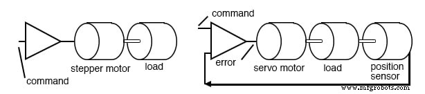
A stepper motor is a digital motor that moves its rotor in discrete steps rather than rotating continuously. When energized but stopped, it holds its load with a reliable holding torque. The widespread adoption of stepper motors in the last two decades was made possible by solid‑state drivers that interface directly with microprocessors, offering a low‑cost, low‑complexity solution for precise motion control.
Servo motors, the predecessor of stepper motors, combine a motor, encoder, and error‑amplifier to provide high‑performance motion control. Their extra components increase cost and complexity, and they are typically reserved for applications that exceed the torque or speed limits of steppers. For most tasks—where moderate speed, good accuracy, and affordability are key—the stepper is the default choice.
Historically, steppers positioned the read‑write heads of floppy drives and were used in early hard drives. Modern hard drives, however, rely on high‑speed voice‑coil servos capable of sub‑millisecond positioning.
Servo amplifiers are linear devices that require careful tuning of gain and phase to match mechanical loads. In contrast, stepper drivers are simple on‑off switches that supply current to windings. This makes stepper control electronics cheaper and easier to design.
Stepper motor vs servo motor
Characteristics
Step‑step motors are rugged and inexpensive because the rotor is a solid cylinder—often a permanent magnet—without slip rings or commutators. The stator is laminated and can contain two to five winding phases. Because they are not designed for continuous rotation, steppers are typically rated in torque rather than horsepower.
- Torque ranges from a few inch‑ounces in tiny “dime‑size” units to over 1,000 inch‑ounces (≈10 N·m) in larger 4 kg motors.
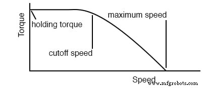
- Speed‑torque curves illustrate that holding torque is high, but available torque drops as speed rises, ultimately reaching zero at a maximum operating speed determined by the motor and load inertia.
- Step angle depends on construction: 90° (4 steps per revolution) to 0.75° (500 steps per revolution). Drivers can halve the step angle via half‑steps.
- Maximum start frequency and pull‑in torque limit how quickly a motor can be accelerated from rest; pull‑out torque governs the maximum load the motor can sustain without losing steps.
Stepper speed characteristics
Types of Stepper Motors
Variable Reluctance
These steppers rely on magnetic flux seeking the lowest reluctance path. The rotor is a soft‑iron cylinder with salient poles; when energized, the rotor aligns with the rotating stator field, minimizing air‑gap length. They have large step angles and produce little detent torque when de‑energized.
Example: a three‑phase variable reluctance motor has a 30° step angle. Its step sequence can be illustrated with a simple on‑off switching pattern, as shown below.
Three‑phase variable reluctance stepper motor
Step angle calculation:
ΘS = 360°/NS, ΘR = 360°/NR, ΘST = ΘR – ΘS
NS = number of stator poles, NR = number of rotor poles
Because the rotor has fewer poles than the stator, the rotor moves a smaller angle per stator step, giving a finer step resolution.
Permanent Magnet
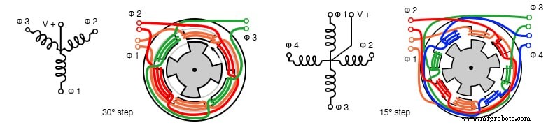
These steppers feature a cylindrical permanent‑magnet rotor. The stator typically has two windings, which may be center‑tapped for a unipolar drive or driven with alternating polarity for a bipolar drive. They exhibit detent torque when de‑energized and have large step angles (often 7.5°–90°).
Drive options:
- Wave drive energizes one coil at a time—simple but lower torque.
- Full step energizes both coils simultaneously—higher torque.
- Half step alternates between wave and full step—doubles resolution.
Unipolar wiring (4‑, 6‑, 5‑, or 8‑wire configurations) allows use of a single polarity supply but requires more driver outputs. Bipolar wiring gives higher torque but needs a more complex driver.
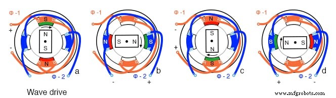
PM wave drive sequence
Typical construction: a 24‑pole can‑stack design with 12 interdigitated fingers per phase, yielding 15° step angles.
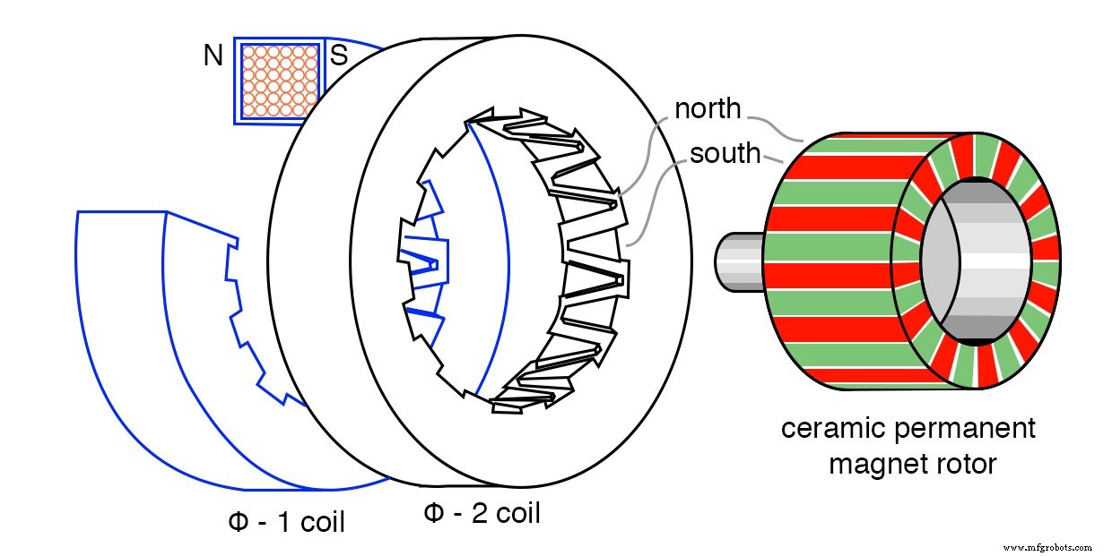
24‑pole can‑stack permanent magnet stepper motor
Hybrid
Hybrid steppers combine the soft‑iron teeth of a variable reluctance motor with the permanent‑magnet core of a PM motor, resulting in a very fine step angle. The rotor has radial soft‑iron teeth offset by half a tooth, while the stator has matching teeth. The two phases are offset by a quarter tooth, allowing the motor to step in 192 positions per revolution in the example shown.
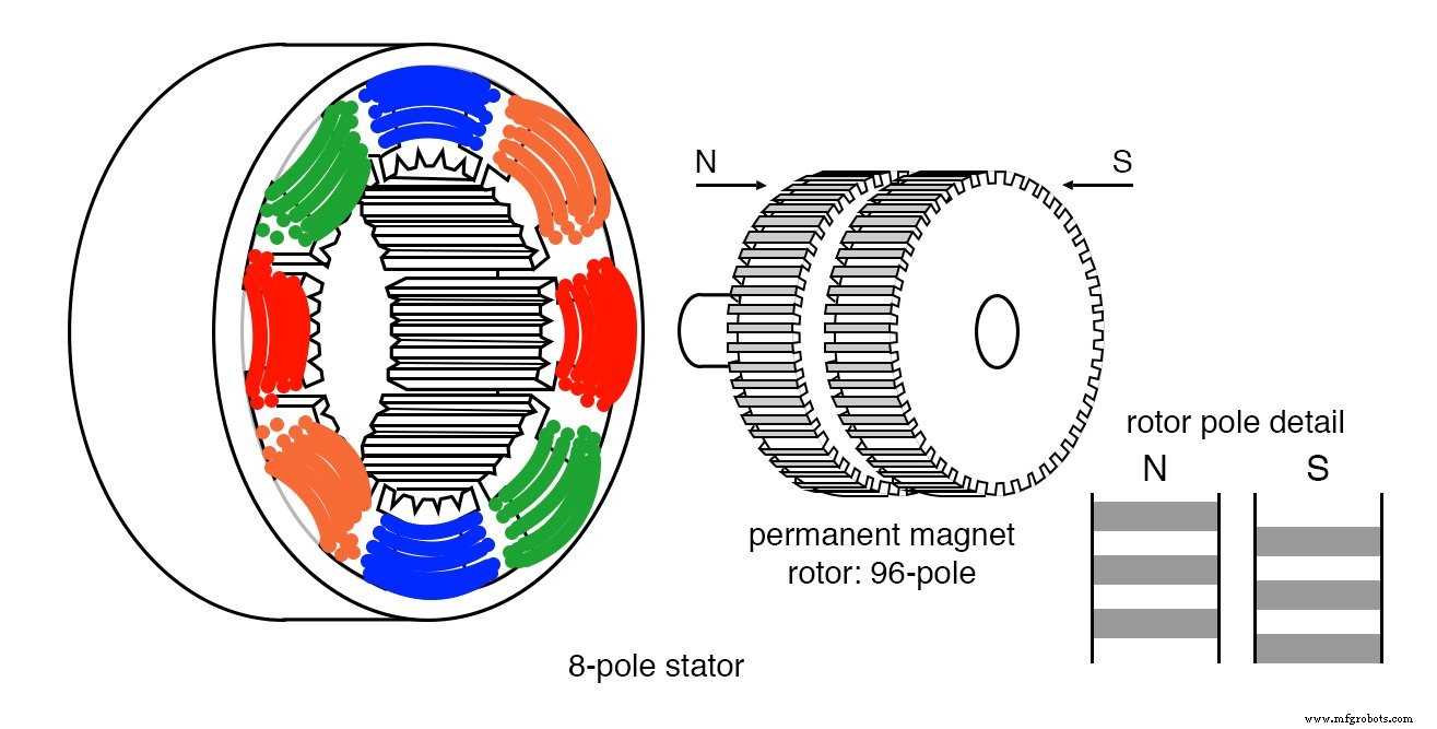
Hybrid stepper motor
Applications
- Floppy disk and early hard‑drive head positioning.
- Printers and copiers (paper advance).
- 3‑D printers, CNC routers, and robotic arms where precise positioning is required.
- Consumer electronics (e.g., camera gimbals, robotic toys).
Summary
- Variable reluctance: soft‑iron rotor, large step angle, no detent torque.
- Permanent magnet: ferrite rotor, can‑stack construction, moderate step angle, detent torque present.
- Hybrid: fine teeth and phase offsets give the smallest step angle and highest resolution.
Choosing the right type depends on required torque, speed, resolution, and cost constraints.
Related Worksheet
Industrial Technology
- Brushless DC Motors: Design, Construction, and Advanced Applications
- Understanding Single‑Phase Induction Motors: Types, Operation, and Efficiency Improvements
- Understanding AC Commutator Motors: Design, Types, and Applications
- Extending Motor Life: Expert Maintenance Tips
- Motor Storage Maintenance: Best Practices to Preserve Performance
- Comprehensive Bipolar Stepper Motor Library for Arduino
- Custom 3D‑Printed Stepper Motor: Build Your Own Precision Drive
- Master DC & Servo Motor Control with Arduino – Step-by-Step Tutorial
- 4 Simple Ways to Keep Your 3D Printer Stepper Motors Cool
- Understanding BLDC Motors: A Professional Guide