


Brushless DC Motors: Design, Construction, and Advanced Applications
The advent of solid‑state power semiconductors enabled the transition from traditional brushed DC motors to brushless DC (BLDC) designs. Although BLDCs are DC devices, their operating principles closely mirror those of AC synchronous motors, making them relevant to any discussion of AC motor technology.
BLDC motors share core similarities with AC synchronous motors; the key distinction lies in the waveform of the back electromotive force (EMF). While synchronous motors generate a sinusoidal back‑EMF, BLDC motors exhibit a rectangular or trapezoidal back‑EMF profile.
In both motor types, a stator generates a rotating magnetic field that interacts with a magnetic rotor to produce torque.
Synchronous motors are typically large, multi‑kilowatt machines, often equipped with electromagnet rotors, and operate at a single speed that is a submultiple of the mains frequency. In contrast, BLDC motors are generally compact, ranging from a few watts to several tens of watts, and rely on permanent‑magnet rotors.
A BLDC motor’s speed is inherently variable unless it is controlled by a phase‑locked loop (PLL) tied to a reference frequency. The typical construction styles are cylindrical or pancake.
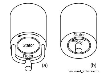
Cylindrical construction: (a) outside rotor, (b) inside rotor
Cylindrical construction is the most prevalent and can be presented in two variants (see figure). The most common variant features an internal rotor, as seen on the right, and is employed in hard‑disk drives. A less common variant places the rotor outside the stator, encircling it.
This external‑rotor arrangement is typical of BLDC fan motors, which often lack a shaft and are compact and robust. In this configuration, the magnetic flux is radial relative to the rotation axis.
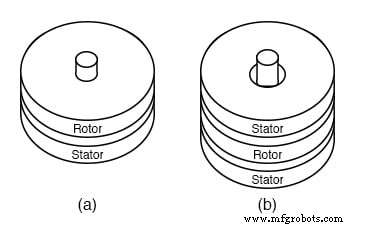
Pancake motor construction: (a) single stator, (b) double stator
High‑torque pancake motors frequently feature stator coils on both sides of the rotor, as shown in figure (b).
Lower‑torque devices, such as floppy‑disk‑drive motors, typically use a single‑sided stator coil (figure (a)). In this arrangement, the magnetic flux runs axially, parallel to the rotation axis.
Commutation can be achieved using various shaft‑position sensors, including optical encoders, magnetic encoders (e.g., resolvers, synchros), or Hall‑effect magnetic sensors. Hall sensors are the preferred choice for small, cost‑effective motors.
A Hall‑effect sensor is a semiconductor device in which the electron flow is influenced by a magnetic field perpendicular to the current direction. It appears as a four‑terminal variable resistor network; the two output voltages are complementary.
When a magnetic field is applied, the sensor produces a small voltage shift at its output. This Hall output can drive a comparator for a stable drive to the power device, or it can drive a compound transistor stage when appropriately biased.
Contemporary Hall sensors often integrate an amplifier and digital logic, making them 3‑lead devices capable of directly driving the power transistor that energizes a phase winding. For accurate position sensing, the sensor must be mounted in close proximity to the permanent‑magnet rotor.

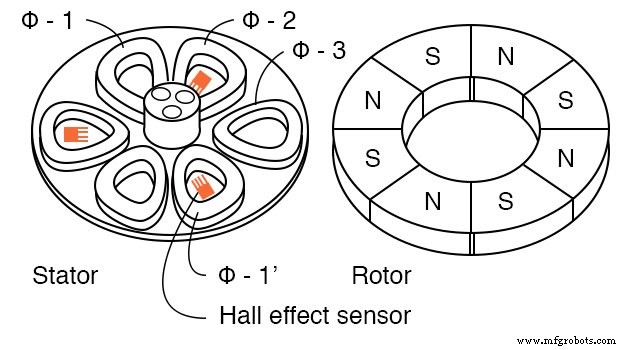
Hall effect sensors commutate 3‑phi brushless DC motor
The basic cylindrical 3‑phase motor (illustrated above) is commutated by a Hall sensor dedicated to each stator phase. As the permanent‑magnet rotor rotates, the Hall device senses the polarity change of the passing rotor pole.
The Hall signal is amplified to ensure the stator coils receive the correct current. In practice, these signals can be processed by combinatorial logic to generate more efficient drive waveforms.
Equipped with a phase‑locked loop (PLL) to regulate speed, this cylindrical motor could drive a hard drive. A similar PLL‑based control could also power a pancake floppy‑disk motor (see figure).
Brushless pancake motor
The 3‑phase pancake motor comprises six stator poles and eight rotor poles. Its rotor is a flat ferrite ring bearing eight axially magnetized alternating poles. Although not depicted, the rotor is capped with a mild‑steel plate that mounts to the bearing in the stator’s center.
The steel plate completes the magnetic circuit, and the stator poles are mounted on a steel plate at the top, further ensuring magnetic continuity.
The flat stator coils are trapezoidal to closely match the rotor poles; the six stator coils constitute three winding phases.
Sequential energization of the three stator phases creates a rotating magnetic field.
The permanent‑magnet rotor aligns with this field, similar to a synchronous motor. A two‑pole rotor would rotate in sync with the magnetic field, whereas an eight‑pole rotor will rotate at a submultiple of the field’s frequency because of the additional poles.
Key features of the brushless DC fan motor include:

Brushless fan motor, 2‑phi
- The stator has 2‑phases distributed between 4‑poles
- There are 4‑salient poles with no windings to eliminate zero‑torque points
- The rotor has four main drive poles
- The rotor has 8‑poles superimposed to help eliminate zero‑torque points
- The Hall effect sensors are spaced at 45° physical
- The fan housing is placed atop the rotor, which is placed over the stator
The primary goal of a BLDC fan motor is cost‑effective manufacturing, encouraging the shift from 3‑phase to 2‑phase designs for lower‑performance products. Depending on its drive scheme, it may also be referred to as a 4‑phase motor.
Traditional brushed DC motors require an odd number of armature poles (3, 5, 7) for self‑starting capability; even counts such as 2 or 4 can result in a torque minimum that hinders starting from rest.
Introducing four small salient poles without windings adds a ripple torque to the torque‑position curve. This ripple mitigates torque minima, enhancing startability.
The additional ripple further eliminates torque minima; as long as these minima do not reach zero, the motor remains startable. The more effectively the minima are suppressed, the easier the starting process.
For a 2‑phase stator, Hall sensors must be electrically 90° apart. With a 2‑pole rotor, this would correspond to a 90° physical spacing; however, our 4‑pole permanent‑magnet rotor requires the sensors to be placed 45° physically to achieve the necessary 90° electrical separation (see Hall spacing above).
Most of the torque originates from the interaction between the inner 2‑phase stator coils and the rotor’s 4‑pole section. Consequently, the 4‑pole section must be positioned at the bottom so that the Hall sensors detect the correct commutation signals.
The additional 8‑pole section is solely intended to improve starting performance.

Brushless DC motor 2‑phi push‑pull drive
The diagram above illustrates a 2‑phase push‑pull (or 4‑phase) drive that uses two Hall sensors to energize four windings. For a single‑pole rotor, the sensors are electrically 90° apart, corresponding to a 90° physical spacing.
Because each Hall sensor produces two complementary outputs, a single sensor can commutate two opposing windings.
Industrial Technology
- Synchronous Motors: Design, Operation, and Applications
- Stepper Motors: Types, Characteristics, and Practical Applications
- Tesla Polyphase Induction Motors: Design, Operation, and Applications
- Wound‑Rotor Induction Motors: Design, Advantages, and Variable‑Speed Applications
- Understanding Single‑Phase Induction Motors: Types, Operation, and Efficiency Improvements
- Specialized Motors: Shaded‑Pole, Servo, Hysteresis, and Eddy‑Current Clutch Applications
- Understanding AC Commutator Motors: Design, Types, and Applications
- Electric Motor Reliability Tip: Reduce Start‑Up Cycles to Protect Your Equipment
- Extending Motor Life: Expert Maintenance Tips
- Understanding Brushed vs. Brushless DC Motors: Fundamentals & Applications